

555 Timer
 knightofoldcode
Posts: 233
knightofoldcode
Posts: 233
Group,
I'm having a wierd issue with the 555, and hopefully someone else much more knowledgable would know what is going on.
About 6 months ago, I breadboarded a circuit for use in a DoorBell system. Using a old style doorbell's bell, and a new Normally Closed alarm contact and a 555, I created a circuit that would allow the door to be opened, the doorbell would ring, then the door could remain open indefinetly. Once closed it would repeat the cycle. After done I just mounted the breadboarded circuit to the wall to get back to it later. Later never came, and the vertical mounting in a breadboard caused the IC, and relay to just fall out. So, now I'm trying to build it onto a PCB. However I'm having some serious issues. In the 555 timer's datasheet it states teh following:
"During the timing cycle when the output is high, the further
application of a trigger pulse will not effect the circuit so long
as the trigger input is returned high at least 10µs before the
end of the timing interval."
I never had to return the triger to high in the past, yet it worked perfect. And now I've made a new board, soldered all the components and as the datasheet says, it's only working if the magnet is put back (thus causing the trigger to go high) before the end of the cycle. If the magnet (trigger line) is kept high or the door is left open, then the output stays high.
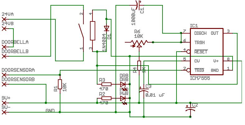
I don't understand how it's not working now, yet worked before? I've got almost the same schematic.... Not exactly, but nothing would be incorrect.... I'll include the working schematic below.
I am trying to set this up in "one shot" mode. With a typical "shot" being LONGER than the timer cycle. Timer cycle being around 2 seconds.....
MUCH TIA,
Knight.
I'm having a wierd issue with the 555, and hopefully someone else much more knowledgable would know what is going on.
About 6 months ago, I breadboarded a circuit for use in a DoorBell system. Using a old style doorbell's bell, and a new Normally Closed alarm contact and a 555, I created a circuit that would allow the door to be opened, the doorbell would ring, then the door could remain open indefinetly. Once closed it would repeat the cycle. After done I just mounted the breadboarded circuit to the wall to get back to it later. Later never came, and the vertical mounting in a breadboard caused the IC, and relay to just fall out. So, now I'm trying to build it onto a PCB. However I'm having some serious issues. In the 555 timer's datasheet it states teh following:
"During the timing cycle when the output is high, the further
application of a trigger pulse will not effect the circuit so long
as the trigger input is returned high at least 10µs before the
end of the timing interval."
I never had to return the triger to high in the past, yet it worked perfect. And now I've made a new board, soldered all the components and as the datasheet says, it's only working if the magnet is put back (thus causing the trigger to go high) before the end of the cycle. If the magnet (trigger line) is kept high or the door is left open, then the output stays high.
I don't understand how it's not working now, yet worked before? I've got almost the same schematic.... Not exactly, but nothing would be incorrect.... I'll include the working schematic below.
I am trying to set this up in "one shot" mode. With a typical "shot" being LONGER than the timer cycle. Timer cycle being around 2 seconds.....
MUCH TIA,
Knight.
787 x 402 - 46K
Comments
i am not shouting. I have been able to read and type all caps much easier for over 50 years.
What do you view that drawing with, i have try'd html, netscape, and thumbs plus and all are blury.......
73
spence
k4kep
The image was exported from a program that I design all of my boards in. The program has freeware versions that are limited to the top and bottom copper layers, and a board dimension, something like 4" by 3", or something like that. I'm not sure what it's size is. I've got the version that allows top and bottom layers and no restrictions on board size. I paid $60 for it, direct from their site. The site is below.
The shcematic above is created with that program, then simply exported.
I don't need anymore than 2 layers as I almost always only use one layer, sometimes two, and I create all my own boards using the Pulsar Method. (Once I get that refined... *grumbles*)
Eagle Layout Editor
Knight.
ROTFLMAO! I misread what you said and I thought you wanted to know what program made it! LMAO!
It's a standard jpg, any picture program should read it without it being blurry. I can reupload in a bmp, or any other image format if needed. It shouldn't be blurry. A small amount of blurry, due to the compression of the jpg, but it shouldn't be much....
Knight.
I've ran this schematic through my head countless numbers of times, and everything is correct. I've ran it through the breadboard and it works right. Unfortunatly, the 555 on the prototype PCB made with the Pulsar.gs system isn't socketed. So I can't just pop the 555 from the breadboard into the prototype board. I guess the next step would be to desolder the 555 from the prototype board and solder in a socket.
I know, sockets are cheap, only $0.10. But I figured I wouldn't need it to come out, ever, and for a $0.30 timer?... I thought it wouldn't be worth it. Not the mention the fact I didn't have any on hand at the time. (Hadn't had a chance to make a digikey order.) Also, I didn't want it to "fall" out. As the IC is hanging vertically. If the socket isn't used to much, it is rather strong connection, but still. I like the stability of soldering it directly. I'm certain I didn't overheat the IC, btw, while soldering. [noparse]:)[/noparse]
Maybe some of the other 555's are made differently. I can't see how, I was pretty certain they were all drop in compatible clones....
If I can't get it working with a 555, I'd really hate to through all the processing power of a MCU at it. (Basic stamp 1, or 2). It just seems wasteful. The stamp would be using two pins. The doorbell sensor and the control of the relay. It just seems like overkill.
The 555 was perfect..... [noparse]:([/noparse]
I'll quite my whinin and see what I can come up with.
If anyone else has any other ideas, instead of having to invest using a BS for this, I'd appreciate it. [noparse]:)[/noparse] I love the Basic Stamps, I just think it's overkill for this application.
Although, if I had to use a BS, it might be kinda neat to be able to remotly tell the BS to NOT ring the doorbell for the next X seconds, that way I can go in or out undetected.
Thanx everyone else for looking,
Knight.
To prevent this, place a small capacitor in series with pin 2. it will charge up and prevent re-triggering
I'm not understanding your recommendation. If a cap is placed on pin 2, there is a 10K pulldown on the line. So the cap would get discharged during the timing cycle, and wouldn't have any charge to bring the line back to high?
Maybe if you could whip up a quick schematic? [noparse]:)[/noparse]
TIA,
Knight.
When all esle fails, assume that this particlar manufacturer has some differences and read the specification for their product. The CMOS versions of the 555 will run on almost nothing, but do not have as high a maximum V+.
▔▔▔▔▔▔▔▔▔▔▔▔▔▔▔▔▔▔▔▔▔▔▔▔
G. Herzog in Taiwan
I've checked that sort of thing as much as I can. [noparse]:)[/noparse]
I've checked both the datasheets for each particular 555, (I've only got two types.)
I've checked for any differences in the datasheet from the type that did work to the type that didn't, and it's the exact same. I've tried one that was the exact same labeling as the one that did work, on the same prototype board, and it doesn't work. So apparantly there is something about THAT particular 555 that is different. Nonetheless, I'm trying to figure out how to use one that is the most common....
I hope I am makin sense here. I want to modify the circuit so that the standard run of the mill 555 will work.
TIA,
Knight.
· You have /TRIG tied low with R1 (10k).· The datasheet states: /TRIG must return to a high state before the OUTPUT can return to a low state (see pg. 5 of attached 7555_int.PDF)· Ideally, /TRIG should return high long before the end of the timing cycle.· Usually the doorswitch holds /TRIG at "9V", but when it opens then·the high at /TRIG is lost and /TRIG stays low and holds OUTPUT high (ON.)·
· I suggest that you go with another timer, a 74HC221; it's a non-retriggerable monostable.··Its output is only edge-triggered (configurable hi-to-lo or lo-to-hi), but otherwise independent of the state of the trigger input.· Therefore,·even if the trigger doesn't change state the output still returns to its normal state (it has Q and /Q.)· In fact, it·ignores any triggers·during the timing cycle (emphasis NON-retriggerable.)
· So, when the door opens: the timing cycle starts and·the output goes high·[noparse][[/noparse]bing-bong!], then it·times out and·the output returns low and stays there (even·once the door is re-closed.)
· Lastly, I wouldn't drive a relay directly from the '221 output (or a 555, or 7555), I'd use a transistor.
Yeah, I know I had the line pulled low, as the datasheet needs, so I mean, I was doing everything right, till I saw the part in the datasheet about it having to return to low before the end of the timing cycle. [noparse];)[/noparse]
I'll really take a look at the 74hc221! It looks like what I'm looking for.... I realize that it's not a good idea to drive the relay directly off of the 555, ohwever for this case I felt it wasn't an issue..... Because 1) I used the diode, 2), the 555 has the capability of a 200milliamp output on it's output. My relay draws 50 milliamp (it's a reed style) and it's got a LED on it, I'm WELL below the limit, on the 74hc221 I'll probably modify it to use a switching transistor. I was trying to keep the component count down, but if I have to add in another resistor, transistor, that's the way it goes.... I'll look into the 74HC221! Much appreciation!
I was hoping to stay with the 555, but it doesn't seem to do what I want.... so I'll likly have to switch.
Just never knew WHAT to switch to. [noparse]:)[/noparse]
MUCH, thanx!
Knight.
Its under Basic Circuits for the LM555
1 Second oneshot monstable oscillator
That circuit will reset even if trigger is kept low, Ive used it myself
almost forgot the link http://home.cogeco.ca/~rpaisley4/LM555.html#5
Knight.
▔▔▔▔▔▔▔▔▔▔▔▔▔▔▔▔▔▔▔▔▔▔▔▔
-=-=-=-=-=-=-=-=-=-=-=-=-=-=-=--=-=-=-=-=-=-=-=-=-=-=-=-
This message transmitted with 100% recycled electrons.
-=-=-=-=-=-
Gravity doesn't exist. The Earth sucks.
-=-=-=-=-=-
Make a man a fire, and he will be warm for the night.
Light the man on fire, and he will be warm for the rest of his life.
-=-=-=-=-=-=-=-=-=-=-=-=-=-=-=--=-=-=-=-=-=-=-=-=-=-=-=-
Being able to put the 555 in a socket is mighty handy.