

Difficult to understand why this simple circuit is not working. help?
 johnbot
Posts: 18
johnbot
Posts: 18
Hi everyone,
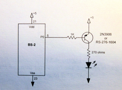
I have a simple question I'm hoping someone can answer. I'm building the very simple attached circuit, attempting to use the 3906 transistor to drive an led. Building the circuit as-is seems to work but if it swap the +5 going into the transistor for another higher voltage powersorce (9 volts), the light, instead of blinking , stays on permenantly. I gounded both power sources together to VSS.
When i simply disconnect and reconnect the base going from the stamp to the transitor it starts acting like a proper switch. When i check the voltage from the pin out of the stamp it's getting +5 and 0 so that seems ok.
The reason I'm using the transistor is to eventually drive a 6 volt light bulb.
Any suggestions?

Post Edited (johnbot) : 4/13/2006 5:34:33 AM GMT
I have a simple question I'm hoping someone can answer. I'm building the very simple attached circuit, attempting to use the 3906 transistor to drive an led. Building the circuit as-is seems to work but if it swap the +5 going into the transistor for another higher voltage powersorce (9 volts), the light, instead of blinking , stays on permenantly. I gounded both power sources together to VSS.
When i simply disconnect and reconnect the base going from the stamp to the transitor it starts acting like a proper switch. When i check the voltage from the pin out of the stamp it's getting +5 and 0 so that seems ok.
The reason I'm using the transistor is to eventually drive a 6 volt light bulb.
Any suggestions?
Post Edited (johnbot) : 4/13/2006 5:34:33 AM GMT
399 x 296 - 58K
Comments
·· The simpler answer is to use a 2N3904 instead.· This will allow you a higher supply voltage for the circuit you're driving.· The reason the circuit isn't working for you on higher voltage is that the Stamp's I/O pin cannot go high enough to effectively turn off the transistor when you power it that way.· Use the 2N3904, use the same resistor (1K) for the base, connect the emitter to ground, and the collector to your load, then the other side to 9V.· Make sure the load can handle 9V.· The LED and resistor value shown won't be compatible.· You will need a bigger resistor for the same LED if you increase the voltage.
▔▔▔▔▔▔▔▔▔▔▔▔▔▔▔▔▔▔▔▔▔▔▔▔
Chris Savage
Parallax Tech Support
csavage@parallax.com
If the I/O pin is LOW, then the equiv circuit would look something like this, and the transistor would be ON...
         1K     B  E
GND >---/\/\-----|<---> +5V
        4.4V    0.6V
If the I/O pin is HIGH, then the equiv circuit would look something like this, and the transistor would be OFF...
         1K     B  E
+5V >---/\/\-----|<---> +5V
         0V      0V
What would happen if you took the +5V connection to the emitter to 9V instead ?
If the I/O pin is LOW, then the equiv circuit would look something like this, and the transistor would be ON...
         1K     B  E
GND >---/\/\-----|<---> +9V
        8.4V    0.6V
If the I/O pin is HIGH, then the equiv circuit would look something like this, and the transistor would be ON...
         1K     B  E
+5V >---/\/\-----|<---> +9V
        3.4V    0.6V
▔▔▔▔▔▔▔▔▔▔▔▔▔▔▔▔▔▔▔▔▔▔▔▔
Beau Schwabe
IC Layout Engineer
Parallax, Inc.
Post Edited (Beau Schwabe (Parallax)) : 10/3/2005 1:57:36 PM GMT
▔▔▔▔▔▔▔▔▔▔▔▔▔▔▔▔▔▔▔▔▔▔▔▔
·1+1=10
▔▔▔▔▔▔▔▔▔▔▔▔▔▔▔▔▔▔▔▔▔▔▔▔
Chris Savage
Parallax Tech Support
csavage@parallax.com
Question, I built a matrixed grid with 122 6 volt bulbs and intended to access them by 22 transistors (11col X 11rows) but realized what i really want to do is control each light instead (since the light bulbs strobe much to slowly for persistance of vision to work). Will someone kindly point me in the right direction for doing this (not asking for a complete answer but maybe a hint). I'm assuming that the pins will have to be multiplexed to give me enough output and then amplified with a ULN2803A?
The project is going to be a very very low res version of a display. I like the idea of using 6v bulbs instead of led's.
·· If you are relying on strobing and POV for your display you will find that light bulbs are much slower than LEDs at lighting up.· This could affect your concept.· You might want to try it on a smaller scale first to get an idea of the performance you can expect.
▔▔▔▔▔▔▔▔▔▔▔▔▔▔▔▔▔▔▔▔▔▔▔▔
Chris Savage
Parallax Tech Support
csavage@parallax.com
▔▔▔▔▔▔▔▔▔▔▔▔▔▔▔▔▔▔▔▔▔▔▔▔
Chris Savage
Parallax Tech Support
csavage@parallax.com
Here's a site that I found useful in explaining transistors.· It even has animated examples and much more.
http://www.williamson-labs.com/480_xtor.htm#darlington
Maybe it'll help.
~Jeff
▔▔▔▔▔▔▔▔▔▔▔▔▔▔▔▔▔▔▔▔▔▔▔▔
P.S. This is what this part of the alphabet would look like if "Q" and "R" were eliminated.
I've created the hardware for my 6 volt light board project and wanted to run the design by to see if I can improve upon it with your suggestions/hints. I currently have the basic stamp sending serial data to 5 shift registers and from there it goes to a few ULN2803 chips and finally to the 5x6 lightboard. I have 7.5V VDD running into the lightboard. I have both the '164 and the ULN2803 running off the same 5V supply (from the basic stamp board) and on the '164s I have pins 1 and 14 tied to positive as noted in the microcontroller cookbook.
Everything seems to work but I suspect there might be a better way to handle the power supply issues since when it's running my stamp indicator led dims on and off depending on how many light bulbs are on. I've attached a very simple jpeg of the basic layout. Should I be including any protective measures or anything else?
Secondly, on the software side.
I've been running a snippet of code from the microcontroller handbook to test the bulbs
for x=1 to 30 'send 30 bits to 164'
toggle 0 'change the bit each time'
high 1 'clock the bit into the 164'
pause 100
next
I've been trying to figure out the best way to send a string of data to the shift registers so i can tell each bulb to be on or off by using an array or something. Ultimately , I would like to do something like this:
data = 0,0,0,1,1,0,0,1,1,1,1,1,1,0,0,1,0 etc, now shift and clock this into the circuit.
Could someone point me to the right command(s), shiftout? or something else?
Thanks!
John
SHIFTOUT is indeed the command you want to use. By using an extended set of data fields (more than 8 bits) so long as the shift registers are daisy chained, you can do it with one command. here is an example:
/code
{$PBASIC 2.5}
'Constants
'Pin Port Assignments (arbitrary)
Clk_Pin PIN 0
Data_Pin PIN 1
'Sample Data ONLY (below)
pattern1 con $FF 'The hex constant can contain any
pattern2 con $0F 'bit configuration(s) you might choose
pattern3 con $F0 'to send out to the shift register
Shift_Mode con 0
SHIFTOUT Data_pin, Clk_pin, Shift_Mode, (pattern1, pattern2, pattern3)
code/
Regards,
Bruce Bates
John
Post Edited (johnbot) : 4/13/2006 2:27:13 AM GMT