

Intel Fun RPM control
 Tricky Nekro
Posts: 218
Tricky Nekro
Posts: 218
I have an Intel Fun and I want to Check It's RPM with the BS2 but I don't know which wire goes where and what command to use ( I expect PULSIN )...
There are four wires a black, a yellow, a blue and a green one...
Definately the black one is the GND...
The Yellow must be the main supply of power...
And the other two must be the input and the output pins...
There must be a way I can debug the output data (RPM)
And .......
If there is no way I can do something, please mention...
Thankfully, Provas, GREECE...
▔▔▔▔▔▔▔▔▔▔▔▔▔▔▔▔▔▔▔▔▔▔▔▔
-Rule your Destiny-
--Be Good. Be Bad. Be Provas--
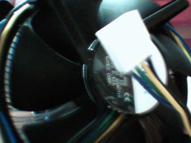
640 x 480 - 138K
Comments
with the 2 other wires
using a scope see if the frequency change's with rpm change
then frequency would be your varible
Here is some general information I found on an Intel web page:
quote
Intel has been aware of customer concerns over increasing fan noise. Intel has now designed a new fan speed control technology to take advantage of the fact that the processor is not always running at its maximum power. This was done by basing the fan speed control on actual CPU temperature and power usage.
The speed of the new fan heatsink is controlled by the additional 4th wire of the fan cable. (The new technology is sometimes referred to as “4-wire fan speed control.”[noparse];)[/noparse]
The additional 4th wire sends a signal from the motherboard to the fan heatsink to control its speed. There is a thermal diode in the processor which measures actual CPU temperature. The processor sends information to the motherboard about its specific thermal requirements and the actual processor temperature. The motherboard then uses this information to optimally control the speed of the processor fan.
end quote
I hope that gives you some general idea what the fourth wire is.
Regards,
Bruce Bates
Actually I've found out that the Green wire is...
Definately it is the pulses and i use the COUNT command to mesure the RPM, but the output is not stable, and i mean really big changes (from 6068 + to 3300) without out any indeference and a stable power supply to the fan... 11.38V DC approximentally...
However, it seems that it works cause when I raise the power to 18.00+ V DC it goes up to 8000RPM but still the result isn't stable...
Here is the code and it "like" the exable code for melexis hall effect sensor...
The other wire looks like a RPM buster to me...·the blue one...
The code:
[color=green]' {$STAMP BS2}
' {$PBASIC 2.5}[/color]

RPM VAR Word
Pulses VAR Word
[color=blue]DO
COUNT[/color] 1, 1000, Pulses
RPM = Pulses * 60
[color=blue]DEBUG[/color] CLS, "[color=red]RPM =[/color] ", [color=purple]DEC[/color] RPM
[color=blue]LOOP[/color]
I was thinking of braking the RPM data to HIGH.Byte and LOW.Byte but this part of code isn't really what I try to specialise in and I know a little bit nothing...
I'm really messed up so I need your imidiate assistance...
Pleazeful, Provas, GREECE...
▔▔▔▔▔▔▔▔▔▔▔▔▔▔▔▔▔▔▔▔▔▔▔▔
-Rule your Destiny-
--Be Good. Be Bad. Be Provas--
must be pwm signal
back probe the fourth wire and see if gives you a square wave pattern
if so
then this will give you information on the duty cycle
8000 rpm at 50 % duty cycle approx 4000 rpm
japer
It must be a booster enable pin which when it goes high it speeds up the rotor and when it goes low the opposite one...
I don't know what else to do, pleaze anyone who know about how to program it, help...
I've tried outputing·data such as rotor speeds ect... but nothing happend...
Pleaze,
Friendly, Provas, GREECE...
▔▔▔▔▔▔▔▔▔▔▔▔▔▔▔▔▔▔▔▔▔▔▔▔
-Rule your Destiny-
--Be Good. Be Bad. Be Provas--