Need Help using DAC0802LCN
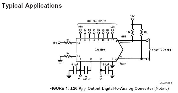
I have managed to hook up this little DAC to the circuit in Figure #1 cache.national.com/ds/DA/DAC0800.pdf
I am confused as to both of the 10V shown on the circuit
Reading the datasheet for the supply voltage pins 3 and 13 it says +18 or 36 volts. Hmmm hard to decide???
I also read the output current says 4.25 mA Does this mean it can drive up to 4.25 mA?
It also says (Vs- = -15V) Is this saying... awww shoot, I can't even guess what that means Maximum -15 volts????
So I am just puzzled
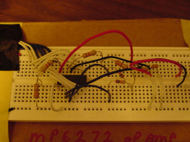
The blue and white wires top left are attached to the basic stamp BS2 pins 8 thru 15
EDIT: OOPS The blue wire for pin #2 shows it on pin#3 I fixed that booboo.
My basic code for testing is this:
Post Edited (metron9) : 9/24/2005 5:33:38 AM GMT
I am confused as to both of the 10V shown on the circuit
Reading the datasheet for the supply voltage pins 3 and 13 it says +18 or 36 volts. Hmmm hard to decide???
I also read the output current says 4.25 mA Does this mean it can drive up to 4.25 mA?
It also says (Vs- = -15V) Is this saying... awww shoot, I can't even guess what that means Maximum -15 volts????
So I am just puzzled

The blue and white wires top left are attached to the basic stamp BS2 pins 8 thru 15
EDIT: OOPS The blue wire for pin #2 shows it on pin#3 I fixed that booboo.
My basic code for testing is this:
' {$STAMP BS2}
' {$PBASIC 2.5}
' {$PORT COM2}
dacbyte VAR Byte
DIRH=255

FOR dacbyte = 0 TO 255
OUTH=dacbyte
PAUSE 100
NEXT

END
Post Edited (metron9) : 9/24/2005 5:33:38 AM GMT


Comments
▔▔▔▔▔▔▔▔▔▔▔▔▔▔▔▔▔▔▔▔▔▔▔▔
Jon Williams
Applications Engineer, Parallax
My thought was you hook up 8 logic pins, a positive voltage and a ground and then just use the voltage at the output. Anyway I have so much to learn about so much I don't need to go plunging ahead with chips that are not well documented so Iwill check out the LTC1257.
Thanks.