

Please help me with the mcp23016 and the bs2px

Hello everyone:
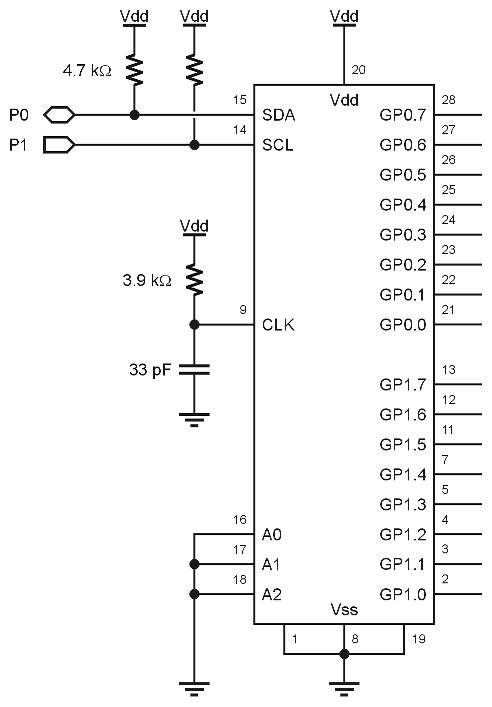
I have gotten my circuit completed using the BS2px, mcp23016 the clock on the mcp23016 is set with a RC circuit the pushbuttons are active low. I don't know if the LEDs have to be configured active low or high. The SDA and SCL have been pulled up with 4.7 ohm resistors and have been designated to p08 and p09 on the BS2px respectively. I'm want all GP0's to be output's. I want all GP1's to be input's. I want each input to have a one-to-one correspondence to the output. Press button one and LED one lights. Press button one and three LED one and three, lights. I am using Jon Williams demo program, I have tried to alter it slightly but I need some help for it to work. Could you look over the program and tell me what is needed for it to work for my application. I have read related data sheets but my understanding is limited.
I2COUT SDA, Wr23016, IODIR0, [noparse][[/noparse]%00000000] ' GP0 pins are outputs
I2COUT SDA, Wr23016, IODIR1, [noparse][[/noparse]%11111111] ' GP1.0 - GP1.7 are inputs
I2COUT SDA, Wr23016, IPOL1, [noparse][[/noparse]%11111111] ' invert inputs
I have attached Jon Williams graphic file of the schematic of how··I setup the mcp23016.
I have attached Jon·Williams slightly altered demo program for your review.
I think the inputs and outputs should be configured like this?
Your help is always appreciated.
Andrew
Post Edited (andrew777) : 9/17/2005 8:07:39 PM GMT
bmp
1019K
Comments
With the MCP23016 you can sink or source a lot of current, so the LED configuration is a matter of choice.· The code -- as I wrote it -- inverts the button inputs so a logic 0 on a pin will put 1 into the corresponding register.· To go 1-for-1, all you have to do is read the input register and write it back to the output address.
· DO
··· I2CIN· SDA, MCP23016, GP1, [noparse][[/noparse]temp]······· ' read inputs
··· I2COUT SDA, MCP23016, GP0, [noparse][[/noparse]temp]······· ' copy to outputs
· LOOP
Let me suggest that you go back to my original demo, hook it up as shown in my schematic, then run and play with that.· If your "understanding is limited" it is better you start with something that works and play with it before you strike out on your own.
▔▔▔▔▔▔▔▔▔▔▔▔▔▔▔▔▔▔▔▔▔▔▔▔
Jon Williams
Applications Engineer, Parallax