

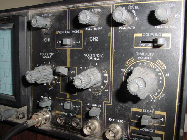
Protek P-2020 20MHZ oscilloscope
 metron9
Posts: 1,100
metron9
Posts: 1,100
I was talking to a friend of mine and mentioned I was looking for an occilloscope He said take this dusty old thing and play with it
Alas no manual and I am a noobe at this.
Can anyone tell me what to set it and how to measure say the voltage on a blinking LED? or some pulseout signals from the BS2?
For now I just want to do something simple.
Thanks
Alas no manual and I am a noobe at this.
Can anyone tell me what to set it and how to measure say the voltage on a blinking LED? or some pulseout signals from the BS2?
For now I just want to do something simple.
Thanks
640 x 480 - 179K
Comments
·· You should be able to Google for a tutorial on using a scope.· You can always check out our docs on the USB Scope!· Might make you want to buy one!·
▔▔▔▔▔▔▔▔▔▔▔▔▔▔▔▔▔▔▔▔▔▔▔▔
Chris Savage
Parallax Tech Support
csavage@parallax.com
Your in luck...··The scope that I "grew up on" was a P-3502 which is very close
What I would probably do first is to buy some "new" test leads.
Next I would self-calibrate the thing just to make sure that it is working.
If you look here:
http://www.protektest.com/ProdDnLd.asp?type=MANUAL
...look for P3502C, this will be the closest to your P2020 and should contain most of the information you will need.
··················
▔▔▔▔▔▔▔▔▔▔▔▔▔▔▔▔▔▔▔▔▔▔▔▔
Beau Schwabe
IC Layout Engineer
Parallax, Inc.
Something wrong with it?
You should get a "flat line" in the DC mode, try adjusting the trigger or press the AUTO/NORMAL button in the trigger section
if you don't see a flat line. Anytime you change the physical position of the scope you should do this because the magnetic
field of the earth can have an effect as well as other surroundings.
I still would invest in a nice set of probes.
The calibration image looks about right... a little long in the TIME domain, but nothing serious
▔▔▔▔▔▔▔▔▔▔▔▔▔▔▔▔▔▔▔▔▔▔▔▔
Beau Schwabe
IC Layout Engineer
Parallax, Inc.
Post Edited (Beau Schwabe (Parallax)) : 8/27/2005 6:01:52 AM GMT
Its set at 5MS Time sweep, The upper line shows 5,4,3,2, and 1 ms pin ON the off cycle is 1ms, at the end is a 5ms wait
I am trying to figure out how to generate a sine wave but alas its 1:00 am again and I better hit the rack. Thanks for the help.
I will post my first generated sign wave when I figure it out, Capacitors will be involved I bet. This is so cool....
I bet I could do timimg studys on individual basic commands during run time, I'll bet you can catch fish with this thing..... whoa....
is an example under the PWM command in the manual using a resistor value of 10K and capacitor value of 0.1uF to convert the
PWM signal into a pseudo analog signal.
BTW) 2:00am here ( baby duty tonight )
▔▔▔▔▔▔▔▔▔▔▔▔▔▔▔▔▔▔▔▔▔▔▔▔
Beau Schwabe
IC Layout Engineer
Parallax, Inc.