

High voltage half bridge
 Paul Baker
Posts: 6,351
Paul Baker
Posts: 6,351
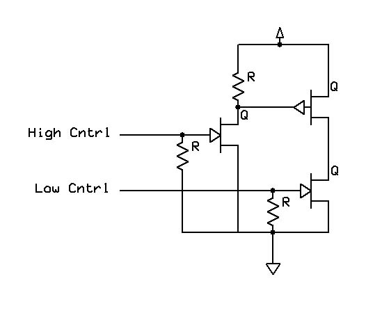
I want a high voltage, high current half bridge. The low side is straight forward, but the high voltage can cause the high side to still conduct even if 5 Volts is applied to the gate. This is the solution I designed and would appreciate feedback on potentialliy easier/cheaper solutions. The nchannel driver for the high side will be a small, standard mosfet, the n and p channel outputs will be the high voltage large current variety.
▔▔▔▔▔▔▔▔▔▔▔▔▔▔▔▔▔▔▔▔▔▔▔▔
·1+1=10
▔▔▔▔▔▔▔▔▔▔▔▔▔▔▔▔▔▔▔▔▔▔▔▔
·1+1=10
549 x 450 - 26K
Comments
Ok let me sub-divide the question: the R in the high side driver (the one connected to Vdd) must be able to properly drive the gate of the high side output PMOS regardless of Vdd. I want to be able to have the bridge operate off of a Vdd between 3-24V. Anyone have guidance for choosing a value for the resistor such that the PMOS will be driven into saturation under all circumstances of Vdd. Vgs(max)=-16V for the PMOS I intend to use. I can brute force calculate the value, but I thought maybe someone may know a shortcut.
Also I am concerned I may need another R below the NMOS used for driving the output PMOS since the Ron of the NMOS will be low compared to the R, meaning in a Vdd= 24V, the Vgs(max) for the PMOS will be exceeded, any thoughts?
▔▔▔▔▔▔▔▔▔▔▔▔▔▔▔▔▔▔▔▔▔▔▔▔
·1+1=10
...Also, for cost, you could use a bipolar in place of the high-side NMOS. (might be cheaper)
▔▔▔▔▔▔▔▔▔▔▔▔▔▔▔▔▔▔▔▔▔▔▔▔
Beau Schwabe
IC Layout Engineer
Parallax, Inc.
··· But I think I may go with a BJT to drive the PMOS, that way I don't have to resort to using numerical analysis to find the quiescent voltage at the drain of a FET.
··· I hadn't thought about using an opto-isolator, since the input of the opto-isolator is electrically isolated from the base of the transitor, how do you calculate what the voltage potential of the base is? I need this in order to determine what values of R to use to set the appropriate voltage at the collector.
··· Also do you or anyone know what the typical isolation voltage of a FET is (gate to drain or source), I know it is lower than an optoisolator but I'd like to to know how many orders of magnitude difference there is between the two.
··· Finally if I used an optoisolator for the PMOS driver, I should also provide one for the NMOS to achieve true isolation, but I'll have 6 of these stages and I'd like to keep the part count and board real estate to a minimum.
▔▔▔▔▔▔▔▔▔▔▔▔▔▔▔▔▔▔▔▔▔▔▔▔
·1+1=10
·
Paul Baker said...
"...since the input of the opto-isolator is electrically isolated from the base of the transitor, how do you calculate what the voltage potential of the base is?"
·
Not sure I understand your question.· If you mean the junction voltage between C-E,·just turn "on" the appropriate transistor and
measure it with a DIODE check on a DVM.· The PS2702's that I have used before is a dual opto package with a transistor output,
and very sensitive towards saturation ( If I remember, saturation could be achieved with a 2.2K current limiting resistor and 5V supply )
·
Paul Baker said...
"Finally if I used an optoisolator for the PMOS driver, I should also provide one for the NMOS to achieve true isolation"
·
I was thinking more towards symmetry.· That's one reason I mentioned a dual.
·
·
For the most part, isolation on the Opto's seems to be about 5kV
·
·
Looking at the DigiKey catalog....
·
http://dkc3.digikey.com/PDF/T052/1475.pdf
·
...I don't see any PS2702-2's, but the PS2502-2 or PS2506-2 should work ok (Darlington output, so the C-E junction should be at least 1.2V instead of 0.6V)
·
There are several options here from pages 1475 to 1484 ( just change the number in the URL )
·
·
▔▔▔▔▔▔▔▔▔▔▔▔▔▔▔▔▔▔▔▔▔▔▔▔
Beau Schwabe
IC Layout Engineer
Parallax, Inc.
I admit if I want to develop this project for commercial purposes I will need to do isolation of the output from the SX, so perhaps I should just bite the bullet, but I would really like to know how to figure what Vb is when the optoisolator is on.
Do FET based opto-isolators exist? If so, perhaps I can combine the isolation and output stages in one.
▔▔▔▔▔▔▔▔▔▔▔▔▔▔▔▔▔▔▔▔▔▔▔▔
·1+1=10
[noparse]/noparse] Current Limiting Resistor Value ][color=white]·[/color]= [noparse][[/noparse] Output Source Voltage - 0.7V[color=white]·[/color](Opto)[color=white]·[/color / [noparse]/noparse][color=white]·[/color]Desired Current[color=white]·[/color
I'm still missing the importance in this case of knowing what·Vb is.· The Voltage at Vce will be·0.7
when the transistor is "on" in saturation, and close to the "Output Source Voltage" when the
transistor is "off".
BTW)
Yes, there is a opto with FET output...
http://dkc3.digikey.com/PDF/T052/1479.pdf
▔▔▔▔▔▔▔▔▔▔▔▔▔▔▔▔▔▔▔▔▔▔▔▔
Beau Schwabe
IC Layout Engineer
Parallax, Inc.
The reason listed above was why I was seeking the voltage on base· in order to determine current flowing through Rb. I think I was confusing the saturation mode of BJTs and FETs, which seem to have different mechanisms for driving the transistor into saturation. Sweet, those may be the ticket, though I'll likely be hard pressed to find one capable of sourcing enough amperes for my project.
Thanks for the schematic, it is superior to the method I was attempting, I like how the bias resistor is used as part of the voltage divider when the optoisolator is active. I also like how the optoisolators are used as a switch (with a diode drop in voltage) making the concern of the base voltage disappear.
Thanks,
Paul
▔▔▔▔▔▔▔▔▔▔▔▔▔▔▔▔▔▔▔▔▔▔▔▔
·1+1=10
maybe, I missed it when reading this thread - how many amperes do you need to source?
Did you ever consider using IGBTs as power switches? In a current project, I'm using IGBTs together with an SX28 to PWM-control two DC motors where each motor can "eat" up to 20 amperes @ 24 volts. I like those Isolated Gate Bipolar Transistors because they combine the typical low-power input control provided by FETs and the low on-resistance provided by bipolar transistors.
▔▔▔▔▔▔▔▔▔▔▔▔▔▔▔▔▔▔▔▔▔▔▔▔
Greetings from Germany,
G
Thanks for pointing out the IGBT, I haven't had the opportunity to work with that variety yet. I'll do some research on them today.
▔▔▔▔▔▔▔▔▔▔▔▔▔▔▔▔▔▔▔▔▔▔▔▔
·1+1=10
Post Edited (Paul Baker) : 8/24/2005 12:59:19 PM GMT
for une of my SX-based applications, I'm using IRG4PC40KD IGBTs from International Rectifier. These devices can handle up to 600V with a typical Vce(on) of 2.1V, an Ic up to 25A, and a maximum power dissipation of 160W @ 25°C, or 65W @ 100°C collector temperature.
The interesting feature of IGBTs is that they combine the advantages of bipolar transistors and Power-FETs. Like bipolar transistors they have a low "on"-resistance, or a low Vce(on), resulting in lower power dissipation. On the other hand, like Power-FETs, they require much less input drive than bipolar transistors. Depending on the IGBT type you are using, you can directly drive its gate from a controller output pin.
The IRG4PC40KD I'm using requires a Vge of about 15V to get "turned on", so I had to add another transistor for driving it from an SX output. Beau's suggestion using opto isolators for level-shifting is a valuable hint. (Beau - thanks for that!)
BTW, for another SX-based application I'm using L6203 full H-bridge drivers from ST. Using a full H-bridge allows you to also reverse the motor direction w/o any electro-mechanical components.
Using a controller, like the SX to generate the PWM signal allows for nice features, like "soft start". For example, I have designed a triple motor controller around an SX 28 with three L6203s. Even when a 100% drive is requested for a motor, the SX increases the PWM from 0 to 100% within a certain period of time (say 250 ms). This avoids the current peaks that would occur when you turn on a motor @ 100% the "hard" way. In my application, this makes it possible to supply all three motors from a single "off-the-shelf" switching power supply which immediately falls into fold-back mode when you try to directly connect one of the motors to its output clamps.
▔▔▔▔▔▔▔▔▔▔▔▔▔▔▔▔▔▔▔▔▔▔▔▔
Greetings from Germany,
Günther