

What did I break and
 doggiedoc
Posts: 2,255
doggiedoc
Posts: 2,255
Hi all! Man I love this site! I have been lurking for a while but now I have a legitimate post. I am not sure if this is a "general electronics and hardware" question or if it belongs in the Basic Stamp Forum or Robotics Forum so I posted it here.
Last week I was assembling my 3rd BOE-Bot. Everything seemed to go just fine. However, a problem arose when I ran my hello world code to check everything out. The editor would not consistently find the Basic Stamp. After checking all of the connections a few times I finally re-seated the Basic Stamp in the socket (by removing and reinstalling it). It would work about 50% of the time. After some frustrating fist banging I swapped out the BS2 with another from one of my other BOE-Bots. That worked flawlessly. Therefore I deduced that I had a bad Stamp or had damaged it on installation. Naturally, when I reinstalled the "bad" stamp the problem returned. With some experimentation I determined that the editor recognized the stamp when I applied a slight amount of pressure to the BS2 with my finger. Figuring it was already toast I experimented with different amounts of pressure in different areas to try to determine if I had a bent or broken pin or the like. Finally I was able to figure out that it wasn't the pressure but the fact that I was touching the stamp and where I touched it. I found that by placing the tip of my finger gently over pins 21 and 22 that the editor would identify the stamp every time.
Ok, so I am no engineer, and my question is this. What connection is my finger providing between pin 21 and pin 22?
I found that a jumper wire did not work and theorized that my finger must have some inherent amount of resistance. So I experimented with a resistor between the two pins and found that lower resistance didn't work whereas higher did.
Ok, I realize that this is long-winded but I wanted to paint a clear picture of what I went through. (It really was quite fun!) I ended up soldering a 1 Meg resistor between the pins. The BOE seems to function fine now. Now problems found yet.
What did I break and "how" did I fix it?
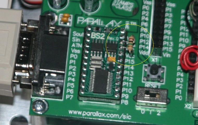
Here is an image of the "fix".
Last week I was assembling my 3rd BOE-Bot. Everything seemed to go just fine. However, a problem arose when I ran my hello world code to check everything out. The editor would not consistently find the Basic Stamp. After checking all of the connections a few times I finally re-seated the Basic Stamp in the socket (by removing and reinstalling it). It would work about 50% of the time. After some frustrating fist banging I swapped out the BS2 with another from one of my other BOE-Bots. That worked flawlessly. Therefore I deduced that I had a bad Stamp or had damaged it on installation. Naturally, when I reinstalled the "bad" stamp the problem returned. With some experimentation I determined that the editor recognized the stamp when I applied a slight amount of pressure to the BS2 with my finger. Figuring it was already toast I experimented with different amounts of pressure in different areas to try to determine if I had a bent or broken pin or the like. Finally I was able to figure out that it wasn't the pressure but the fact that I was touching the stamp and where I touched it. I found that by placing the tip of my finger gently over pins 21 and 22 that the editor would identify the stamp every time.
Ok, so I am no engineer, and my question is this. What connection is my finger providing between pin 21 and pin 22?
I found that a jumper wire did not work and theorized that my finger must have some inherent amount of resistance. So I experimented with a resistor between the two pins and found that lower resistance didn't work whereas higher did.
Ok, I realize that this is long-winded but I wanted to paint a clear picture of what I went through. (It really was quite fun!) I ended up soldering a 1 Meg resistor between the pins. The BOE seems to function fine now. Now problems found yet.
What did I break and "how" did I fix it?
Here is an image of the "fix".
Comments
First of all, Welcome!!
Pin 21 is VDD ( Regulated 5V supply from on board regulator)
Pin 22 is the reset which connects directly to pin 28 (Reset) on the PBasic IC and also
to the output of the brown out detector.
1 Meg seems really high for much of anything here. My suspicion is that the brown out
detector is damaged somehow.
Can you measure the voltage between pins 22 (RESET) and 23 (VSS) and let me know
what that is?
I can check it tomorrow against what it should be.
www.parallax.com/dl/docs/prod/schem/BS2RevF.pdf
▔▔▔▔▔▔▔▔▔▔▔▔▔▔▔▔▔▔▔▔▔▔▔▔
Beau Schwabe
IC Layout Engineer
Parallax, Inc.
Thanks for the fast reply and warm welcome! I tested the voltage accross pins 22 and 23 and got 4.54 volts. Then I desoldered the resistor you see in the previous image and got a fluctuating voltage that started with few milivolts and ramped up to about 1.5 volts then started over again. I soldered the 1 Meg restistor back and got 4.54 volts again.
This is really over my head but I like to know "the why" behind things. Silly huh?
This is a generally accepted configuration since power gets interrupted and an automatic reset is usual under those circumstances.
Also, the Reset pin has a Pull-up resistor usually attached to prevent spurious resets.· From what you describe, it sounds like you damaged the pull-up resistor and while 1-meg is a very high and conservative value, it has managed to provide you with a re-established function.
At least, that is my guess.· Having read from the Web site for some time, I think Beau is one of the sharpest engineers available.· If he comes up with something else, it is probably well founded.
Your too humble.· Your approach to the problem was pretty good and conservative.· I think a lot of people would have just trashed the Stamp and not tried for a good fix.
▔▔▔▔▔▔▔▔▔▔▔▔▔▔▔▔▔▔▔▔▔▔▔▔
G. Herzog in Taiwan
·· The RESET pin is internally pulled HIGH (~+5VDC).· In your case it seems as if the resistor, although an abnormally high value, has corrected the issue.· If you have a problem with a Stamp Module in the future, please call Tech Support and we can help you diagnose the problem.· If the Stamp Module is defective in some way such as this, we could replace it.· But soldering to the Module voids the warranty.
·· If you have any further problems with this module, please call me at Parallax Tech Support and I will see what other options we have for you.· Take care.
▔▔▔▔▔▔▔▔▔▔▔▔▔▔▔▔▔▔▔▔▔▔▔▔
Chris Savage
Parallax Tech Support
csavage@parallax.com
I made the assumption (probably wrongly) that my finger has a lot of resistence and didn't experiment with many lower value resistors.
The thought of warranty issues never crossed my mind.
Heck - I use Mac OS in a Windows world: I am used to having to make things work where they don't usually!
If I had one wish - it would be that RadioShack stocked more Parallax inventory!!!
The voltage readings should be approx...
1.5V - pin 1 (Sout) and pin 23 (Vss)
1.1V - pin 2 (Sin) and pin 23 (Vss)
5.0V - pin 22 (Reset) and pin 23 (Vss)
5.0V - pin 21 (Vdd) and pin 23 (Vss)
...Still not sure why you could not use a lower resistor value of 10K or so.
Thanks for the plug Krammer, although this time I am at a loss... Cold solder joint on pull-up resistors?
(located in the upper left corner of the BS2 - see schematic for reference)
▔▔▔▔▔▔▔▔▔▔▔▔▔▔▔▔▔▔▔▔▔▔▔▔
Beau Schwabe
IC Layout Engineer
Parallax, Inc.
With it the way it is now I get: (my other two Bots for comparison)
BS2a BS2b BS2c
0.00V 0.00V 0.00V - pins 1/23
0.00V 0.00V 0.00V - pins 2/23
5.00V 5.00V 4.54V - pins 22/23
5.00V 5.01V 4.98V - pins 21/23
BS2c is the BOE in question. All 3 BOEs set to pos 1 on the power selector.
I am not sure if I am using the meter correctly. I can't seem to get 1.5V across pins 1 and 23, or 1.1V across 2 and 23 on any of the Bots - could it be my methods?
Bean.
▔▔▔▔▔▔▔▔▔▔▔▔▔▔▔▔▔▔▔▔▔▔▔▔
"SX-Video·Module" Now available from Parallax for only $28.95
http://www.parallax.com/detail.asp?product_id=30012
Product web site: www.sxvm.com
"One experiment is worth a thousand theories"
·
▔▔▔▔▔▔▔▔▔▔▔▔▔▔▔▔▔▔▔▔▔▔▔▔
Beau Schwabe
IC Layout Engineer
Parallax, Inc.
Ah yes, there I go again - my ignorance was hanging out again...
3.74V across pins 1 and 23 on Stamp in Question
3.74V across pins 1 and 23 on good BOE
7.70V across pins 2 and 23 on Stamp in Question
7.69V across pins 2 and 23 on good BOE
4.98V across pins 21 and 23 on Stamp in Question
5.01V across pins 21 and 23 on good BOE
4.98V across pins 22 and 23 on Stamp in Question
5.01V across pins 22 and 23 on good BOE
-these values with both BOEs powered up with 6V battery pack and serial cable connected thru USB adapter
-also these values are with a 10Kohms resistor soldered between pins 22 and 23 on the Stamp in Question.
Looks ok, huh?
Let me check this again, I might have goofed!! (Stamp might have been sending something via DEBUG command)
▔▔▔▔▔▔▔▔▔▔▔▔▔▔▔▔▔▔▔▔▔▔▔▔
Beau Schwabe
IC Layout Engineer
Parallax, Inc.
It's late and I think my brain left about an hour ago....
When I finally got the engine out, I found that I had a bad oil pressure gauge. The engine was sound.
We all tend to be too intellectual about repairs. And, I personally get too tired to keep all these bits and bytes straight.
If the 1 meg resistor works fine, I would just use it as a spare and make a note of how it is functioning. If it fails again, I'd try something different.
I had another 53' Chevy Pickup that I started to completely rebuild the engine. I wanted to learn to be an expert engine rebuilder. The machine shop and parts house handed me an estimated total cost of $750 [noparse][[/noparse]more than a new engine!], so I bought another used mystery engine for $50 and forgot about it. Though it leaked a bit of oil, I was way ahead of the game.
(The fact is I had about 6 of these old pickups and they really taught me that any device has a personality which if understood and respected will serve adequately. Now, I just expect cars to stop, to steer, and keep their wheels on.)
The real question is, 'Is this BasicStamp safe to use in a normal circuit?'
For me, it would seem so. After all, it isn't putting out an abnormally high voltage or current.
On the other hand, I seem to be building very little, but immensely enjoying puzzling over these devices. Best wishes.
▔▔▔▔▔▔▔▔▔▔▔▔▔▔▔▔▔▔▔▔▔▔▔▔
G. Herzog in Taiwan
Well my plan was to put it through the paces last night but I got side-tracked printing What's a Microcontroller? and the BASIC Stamp Syntax and Reference Manual on two sides and punching all the holes for binders! They look great and are perfect for reading and making notes in the margins now, but I am too tired to focus on learning. Ironic?
Anyway - I really appreciate everyone's input on this. I have quite enjoyed the troubleshooting. Now it's time to get to the intended use for these little buggers - programming them to do really cool "stuff"!
Thanks all,
Paul