

Creative solutions to a simple problem?
 khalidasweila
Posts: 9
khalidasweila
Posts: 9
Components involved:
16x 3v 350mA LED's
1 x Stamp Homework Board
2 x Darlington Array
Assorted Resistors
Project:
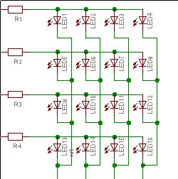
Control any or all of the 16 led's in the matrix (see schematic below) by turning R1...4 high, and G1....4 to low.

Problem:
Each of the LED's need 350mA to turn their brightest, since the STAMP can only allow for 20mA per channel, I need to integrate the Darlington array to switch a bigger power supply.
Issue:
Unclear how to wire the darlington array since I think I need one to supply the 3v, 350mA positive to the LED's and another in the inverse to sink the ground (since the STAMP can only sink 25mA)....
Thanks for taking a moment to read this [noparse]:)[/noparse]
~zev
16x 3v 350mA LED's
1 x Stamp Homework Board
2 x Darlington Array
Assorted Resistors
Project:
Control any or all of the 16 led's in the matrix (see schematic below) by turning R1...4 high, and G1....4 to low.
Problem:
Each of the LED's need 350mA to turn their brightest, since the STAMP can only allow for 20mA per channel, I need to integrate the Darlington array to switch a bigger power supply.
Issue:
Unclear how to wire the darlington array since I think I need one to supply the 3v, 350mA positive to the LED's and another in the inverse to sink the ground (since the STAMP can only sink 25mA)....
Thanks for taking a moment to read this [noparse]:)[/noparse]
~zev
250 x 252 - 20K
Comments
PNP darlingtons don't come in arrays that I am aware of (if so they are rare). You can use npn darlingtons for the high side as well as the low side, but I dont know if this is true for arrays or just individual darlingtons (need acrobat). You must be trying to drive some pretty hefty LEDs, the 1 watt luxeons take 350mA and they are blinding.
If I were to design the circuit, I would connect an array to the column lines and get 4 pnp darlingtons capable of handling 1.5A to drive the Row lines. Ill explain the reason for the bigger pnps in a bit. You're going to need to do multiplexing to drive all the LEDs, otherwise youd need 16 seperate darlingtons to drive all the LEDs. The circuit you've provided uses a total of 8, but requires multiplexing to drive the LEDs. To reduce flickering of the display, drive a single row high while pulling all the columns where an·LED is lit in that row down. Then the same is repeated for all rows, so for the pattern:
We would activate the pnp darlington for row 0, then drive the column 0 and column 3 npn darlingtons low. Then·do the same for each·Row, only·activating a single pnp darlington at a time. The goal is to do it so fast that it appears like its being lit all at once. So since all four LEDs on a row may be lit the same time, the pnp darlington has to handle 4 times the current·of an LED, or 1.05 A (get·slightly higher to have a margin of safety). Also move the resistors down to the columns to prevent fluctuations in LED brightness due to·a variable load resistance.
Ask for clarification or further detail where needed.
▔▔▔▔▔▔▔▔▔▔▔▔▔▔▔▔▔▔▔▔▔▔▔▔
·1+1=10
Post Edited (Paul Baker) : 8/18/2005 3:21:27 AM GMT
▔▔▔▔▔▔▔▔▔▔▔▔▔▔▔▔▔▔▔▔▔▔▔▔
Chris Savage
Parallax Tech Support
csavage@parallax.com
you would only need four of them, they are surface mount (SM8), however the pitch is slightly different than normal ( 1.53mm) . I have used these in
the past and have been pleased with the results. ...any one of them on the link below would work.
http://www.zetex.com/3.0/b2-5c.asp
▔▔▔▔▔▔▔▔▔▔▔▔▔▔▔▔▔▔▔▔▔▔▔▔
Beau Schwabe
IC Layout Engineer
Parallax, Inc.
Lee Harker
▔▔▔▔▔▔▔▔▔▔▔▔▔▔▔▔▔▔▔▔▔▔▔▔
·1+1=10
▔▔▔▔▔▔▔▔▔▔▔▔▔▔▔▔▔▔▔▔▔▔▔▔
Sid Weaver
Do you have a Stamp Tester yet?
http://hometown.aol.com/newzed/index.html
·
▔▔▔▔▔▔▔▔▔▔▔▔▔▔▔▔▔▔▔▔▔▔▔▔
Chris Savage
Parallax Tech Support
csavage@parallax.com
For each LED you want
      ^ Vdd
      |
      |
     ---
     \ /
      V
     ---
      |
      |            ____________________
--------------    |    Shift Register  |--- SI
| darlington |----|Q0     74HC595      |--- SCK
--------------    |____________________|--- RCK
      |
     ---
      -
where subsequent darlingtons are connected to Q1-Q7, if you haven't purchased darlingtons yet get the TPIC6595 which incorporates the darlington into the shift register. Connect the SO pin of the first 74hc595/tpic6595 to the SI pin of the second 74hc595/tpic6595.
And dont forget the current limiting resistor, also since all 8 darlingtons may be active simultaneously, check the max total current of the darlington to make sure your not overdrawing from the darlington, if so you can use two channels for each LED to cut the current drawn by half.
▔▔▔▔▔▔▔▔▔▔▔▔▔▔▔▔▔▔▔▔▔▔▔▔
·1+1=10
Post Edited (Paul Baker) : 8/19/2005 4:37:42 PM GMT
▔▔▔▔▔▔▔▔▔▔▔▔▔▔▔▔▔▔▔▔▔▔▔▔
·1+1=10
The darlingtons will contribute some voltage drop but maybe some series diodes (or something else?) will be necessary.
What colors are you using? The blues, greens, and whites have a Vf of about 3.4V. The reds, oranges, and ambers have a Vf of about 2.1V.
Chris I.
PS you cannot connect one of the terminals of the LED (anode or cathode) to a common terminal (VCC or ground respectively) if you are using the grid configuration. This will cause the whole row or column (depending on how you have it set up) to light up. An advantage of using this over the shift register idea is that PWM implementation to control the brightness will be easier once the hardware is connected properly. I'm implementing this on an FPGA, so i dont know what hte ramifications of this will be on your stamp processor.
I hope I have been of some help,
Furqaan