

rctime problem
 les nesman
Posts: 9
les nesman
Posts: 9
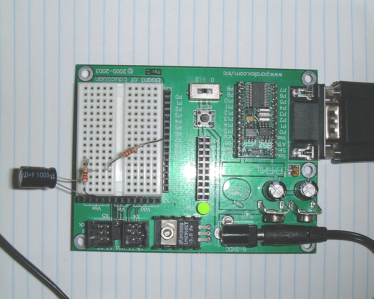
DetailedProblem=I'm trying to set up the stamp to be an ohmeter.
I will be measuring resistance in the range of 100-200 ohms
As a test I use a 1000 micro farad cap and a 220 ohm resistor.
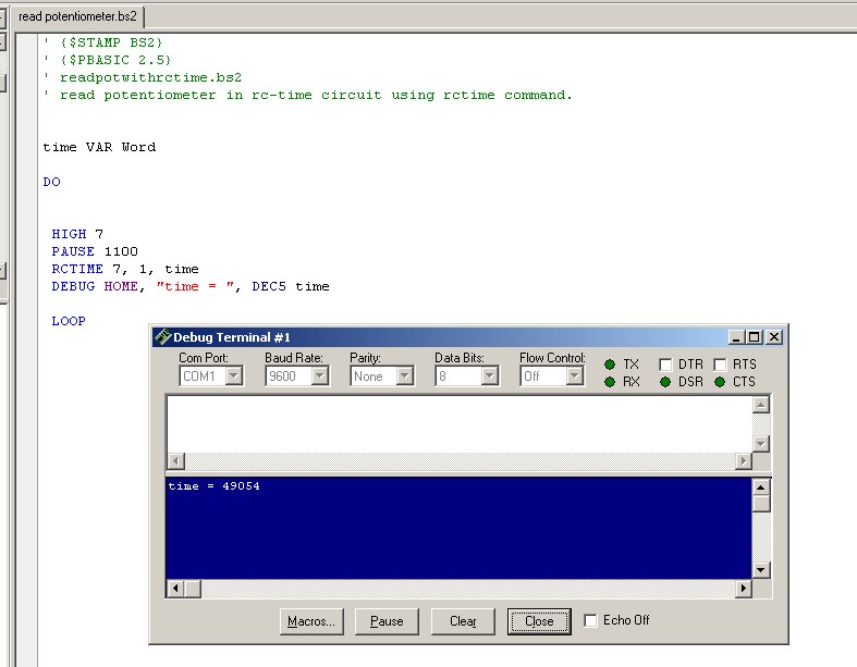
When i run the program the rctime = 48000
Using the equation from the Basic Stamp reference manual.
Rctime units = 635 x R (inKOhms)xC (mF)
so R = rctime/635*C
R = 48000/635*1000 = .075kohms =75 Ohms
That's pretty far off. What am I missing here?
A picture of the circuit and a screenshot of my program/debug window are attached.
Thanks -Keith
I will be measuring resistance in the range of 100-200 ohms
As a test I use a 1000 micro farad cap and a 220 ohm resistor.
When i run the program the rctime = 48000
Using the equation from the Basic Stamp reference manual.
Rctime units = 635 x R (inKOhms)xC (mF)
so R = rctime/635*C
R = 48000/635*1000 = .075kohms =75 Ohms
That's pretty far off. What am I missing here?
A picture of the circuit and a screenshot of my program/debug window are attached.
Thanks -Keith
1280 x 1024 - 531K
787 x 613 - 56K
Comments
▔▔▔▔▔▔▔▔▔▔▔▔▔▔▔▔▔▔▔▔▔▔▔▔
Jon Williams
Applications Engineer, Parallax
So C=rctime/(635*.216) = 356mF
Now I replace the 216 ohm resistor with a coil that measures 157ohms on my digital ohmeter.
The rctime is 19834. I plug it into the equation.
R = rctime/(635*C) = 19834/(635*356) = .087 kohms
Something is still funky??
Thanks -keith
And electrolytics are known for lots of leakage current.· You probably want to use a ceramic capacitor.
Post Edited (allanlane5) : 8/17/2005 2:43:36 PM GMT
The only other resistor I have is about 420 ohms and that drives the rctime
over 65000 so it defaults to zero.
So I figured since I had coils that measure around 157 ohms. I would use those as a test to
see how the ohmmeter works. Sounds like that wasn't such a good idea. Please explain why an inductor would make the rctime be so far off?? Thanks.
I have no clue what is happing here. Please help.
·· Could you try a known configuration?· Please try a 10K resistor with a .1uF cap.· This will go to the I/O pin through a 220 ohm resistor.· PAUSE value will be 1.· See what you get then.·
▔▔▔▔▔▔▔▔▔▔▔▔▔▔▔▔▔▔▔▔▔▔▔▔
Chris Savage
Parallax Tech Support
csavage@parallax.com
▔▔▔▔▔▔▔▔▔▔▔▔▔▔▔▔▔▔▔▔▔▔▔▔
Chris Savage
Parallax Tech Support
csavage@parallax.com
similar to what is described above.
Perhaps the question should be asked.· Do you need to measure the resistance of an inductor?· If so, then the attached schematic will produce aproximately 0.01 Volts
per Ohm with a resistor or inductor.· To measure the voltage you will need to use an ADC of some kind.
·
In contrast, see· http://www.greenandwhite.net/~chbut/rc_cir.htm· for an RC comparison.
▔▔▔▔▔▔▔▔▔▔▔▔▔▔▔▔▔▔▔▔▔▔▔▔
Beau Schwabe
IC Layout Engineer
Parallax, Inc.
Post Edited (Beau Schwabe (Parallax)) : 8/17/2005 4:43:48 PM GMT
I tried using the .1mF cap and 10 k resistor. rctime = 688.
So that works well.
In response to Beau.
Yes, I was building the application to measure the resistance of solenoid coils. Will setting up the attached circuit with an analog to digital converter be pretty straightforward or do you have to be pretty experienced to make that fly? Obviously I'm a·very electronically challenged if I can be stumped by rctime
There are several ways that your goal can be accomplished some are better than others. The circuit that I provided simply converts resistance
into voltage ( I thought that might be easier to deal with ) using as easy to find components I could think of. In theory you can directly use an
ADC without my circuit by placing the resistor in question across a voltage divider, but with the relatively low resistance values you are looking
at, the range will be limited.
There are several "how to's" here in the forum as well as in the Stamp manual on how to use an ADC.
▔▔▔▔▔▔▔▔▔▔▔▔▔▔▔▔▔▔▔▔▔▔▔▔
Beau Schwabe
IC Layout Engineer
Parallax, Inc.
Post Edited (Beau Schwabe (Parallax)) : 8/17/2005 5:54:20 PM GMT
R_unknown = RCT_value / constant - 1000
         220          1k     DUT
  P0 --/\/\--o----/\/\---/\/\----.
               |                         |
               '-----||-------------o- Vss
                      1 uF
That does not account for the output resistance of the Stamp (around 30 ohms for an SX chip, higher for a PIC), nor for the 220 ohm resistor in series with the pin, which is there to protect the pin from the large discharge current of the 1uf capacitor as well as to protect it from ESD from outside that might come in from outside in a test
The formula is,
1.3 = 5*exp(-tm/(R*C)) ' on a calculator (not stamp math!)
Where 1.3 volts is the Stamp threshold, 5 is the Stamp Vdd supply, tm is the time it takes for the capacitor to discharge from 5 volts down to 1.3 volts, and R and C are the parameters. However, that assumes that the capacitor is discharging from 5 volts, which is only a good approximation when the resistance R of the Device Under Test is much much larger than the output resistance of the Stamp. Otherwise, it starts from,
V = 5 * (R / (R + 220 + Rout)
where Rout is the output resistance of the Stamp and 220 is the protection resistor. Substituting 50 ohms for Rout, the starting voltage is,
V = 5* (1000/(1270) = 3.93 volts.
So, the RCtime value will be considerably shorter than you would expect from the generic formula that is valid when the resistance is high. When R is variable, that has to be accounted for in the formula, which complicates it greatly:
1.3 = (5 * (R / (R+220+Rout)) * exp(-tm/(R*C)) ' on a calculator (not stamp math!)
It is really a lot better for calculations if you can use a larger resistor and a smaller capacitor. Say, a 10k ohm minimum and a 100 ohm protection resistor and a 0.1uf capacitor. That will give times around 1000 microseconds (rctime values of 500 on the BS2, higher on the other stamps).
         100        10k     DUT
  P0 --/\/\--o----/\/\---/\/\----.
               |                         |
               '-----||-------------o- Vss
                      0.1 uF
The error from the output and protection resistance is less than 1%, and a much smaller fraction of the total.
Here is a URL with more RCTIME tutorials:
emesys.com/BS2rct.htm
▔▔▔▔▔▔▔▔▔▔▔▔▔▔▔▔▔▔▔▔▔▔▔▔
Tracy Allen
www.emesystems.com
Post Edited (Tracy Allen) : 8/20/2005 6:55:48 PM GMT
What happened to 100 Ohms to 200 Ohms?·
You might be able to implement something like this and have two seperate scales.
0-300 Ohm and 200-500Ohm (small overlap)
Note:
Calibrate by setting the scale and placing the LOWEST resistance value for that scale in the appropriate place.
Adjust the Rcal for that scale until you read 1 Volt.· done!
▔▔▔▔▔▔▔▔▔▔▔▔▔▔▔▔▔▔▔▔▔▔▔▔
Beau Schwabe
IC Layout Engineer
Parallax, Inc.
Post Edited (Beau Schwabe (Parallax)) : 8/17/2005 11:19:00 PM GMT
Thanks for the great explanation of why rctime can't measure a small resistance. I am going to try the 10k resistor idea. -Keith
i = Vi / Rdut enforced by feedback op-amp
The transistor can be either a logic tye mosfet or a pnp (high beta preferable). The current through the resistor equals the current through the capacitor, which charges at a linear rate,
i = C dV/dt => dV = i dt / C charging C
Intagrated, the voltage at the Stamp pin is,
Vout = Vo - (i * t / C) Vo is initial condition
= Vo - Vi/(Rdut*C) * t
The voltage would start at 5 volts and go down to the Stamp threshold at 1.3 volts, a total of 3.7 volts change, in RCTIME 0,1,result.
Then with Vi=0.1 volt and choosing C=0.1µf,
Vout = Vo - t/Rdut t in microseconds,
substituting Vo=5 volts, Vout=1.3 volt threshold
Rdut = t / 3.7
The op-amp has to be a single supply type, and preferably one with a small offset voltage. The LM358 would work, but more modern precision op amps like the LT1078 would be better. Best if it can swing rail to rail at the output.
▔▔▔▔▔▔▔▔▔▔▔▔▔▔▔▔▔▔▔▔▔▔▔▔
Tracy Allen
www.emesystems.com
Post Edited (Tracy Allen) : 8/20/2005 7:04:42 PM GMT