

OptoIsolation and RS232 issue
 KoyJa
Posts: 17
KoyJa
Posts: 17
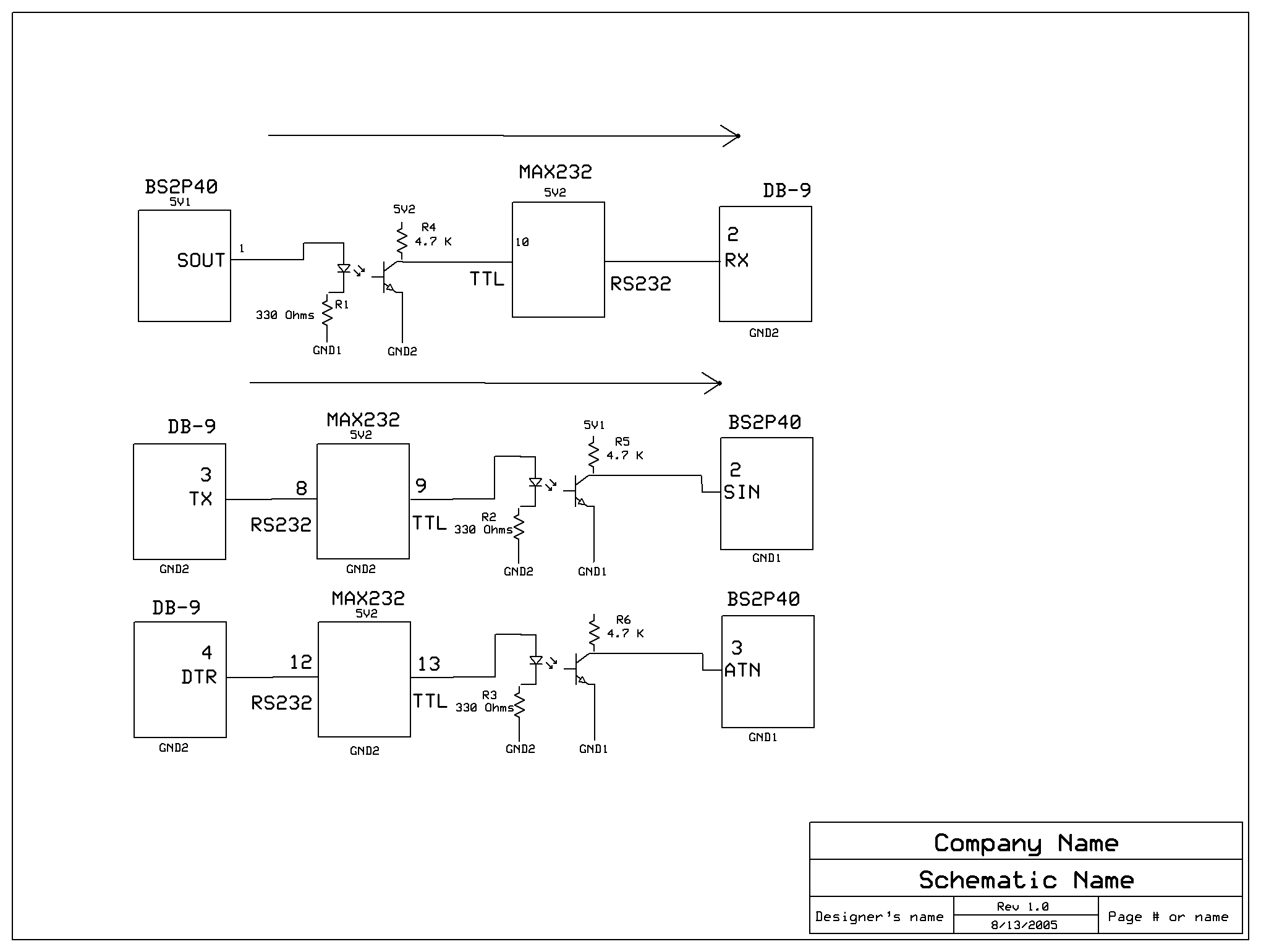
Im having an issue with a PCB I mad using the BSP240. To eliminate the 60Hz noise
coming accross the RS232 port I have Optically Isolated the Stamp serial port
from the DB9 RS232, I am also using a DC/DC converter to give me seperate rails
5V1 GND1 (STAMP) 5V2 GND2 (RS232). I can send data to the Debug screen with no
Issues, this works great. My problem is I am not able to Identify or program the Stamp
(I have to connect directly to the Stamp with 4 header pins to program it)
I have attached a schematic for reference :
The MAX232 Im using gives me the proper voltages the Pumps are working (+10 -10)
and like I mentioned before I can send data to the Debug Window. I also tried putting
a .1uf cap Inline with the DTR Pin like it shows in the Manual, but it still doesnt work.
All static volatges with the conector on seem to be·fine .... however since Im using
an R2232 driver the output is TTL levels .... so I have .125mv on all pins instead of·~ -8.0v
if I were to·connecting directly to the Serial port. If anyone has tried this before I would
appreciate any advice.
Thanks
mike
KoyJa
Comments
·· The BASIC Stamp pins can handle the RS232 voltages directly, but now you're feeding them through both a MAX232 and an opto-isolator.· That's got to be messing with the signals in a bad way.· If you were having a problem with a 60hz noise, you should've handled that another way than to convert the signals going in/out the Stamp Module twice.· I'd really have to do some thinking just to decide if the right signals are coming/going from the Stamp Module at this point.
▔▔▔▔▔▔▔▔▔▔▔▔▔▔▔▔▔▔▔▔▔▔▔▔
Chris Savage
Parallax Tech Support
csavage@parallax.com
Thanks for your reply. I am not going through the STAMP twice with my signals. I am however like you pointed out
inverting the signals twice to get the same signal if I didnt use the max232 and opto staright TTL level·:
---· 10V TX DB9
> 10V 232In
> 0V 232out to Opto in ---- 5V Optout switch open ----> 5V to Pin2 Stamp SIN
As my schematic shows the same setup is used for the DTR to ATN Path.
The schematic shows using a .1uf cap on the DTR line, however I believe I cant do this because I have Isolation
implemented. Im thinking I have a rest issue .... can you supply me a techinal detail why these .1uf caps are used?
Thanks
mike
KoyJa
·· The reason for the .1uF caps on the DTR/ATN ine is that some computers hold the DTR line high when the port is idle.· Some software does this as well.· When this happens the Stamp Module is held in a RESET state, since a high on the DTR/ATN lines holds the RESET line LOW.· The cap prevents the line from being held (Blocks DC).·
·· Two possibilities exist though to defeat this.· One is that the line is toggling.· Rarely this has been seen on some computers and the only thing to do then is unplug the cable after programming.· The other is on your case, if you have noise, it could be affecting the circuit, rendering it useless.
·· Just because you have isolation does not mean you cannot use the capacitor.· It can still be connected between the ATN line and whatever is driving it.· However, I believe in your signal conversions (Of which you are doing twice, that I was referring to) you could be conflicting either with the timing, and/or the proper signal levels to properly program the Stamp Module.
▔▔▔▔▔▔▔▔▔▔▔▔▔▔▔▔▔▔▔▔▔▔▔▔
Chris Savage
Parallax Tech Support
csavage@parallax.com
a timing diagram for the "Identify Sequence" ..... hmmmm good excuse to get a 4 channel
scope.
Thanks again
mike
KoyJa
This is what the MAX232 expects and will take the true TTL data and "RS-232" it (which inverts it and pumps it to 10/12volts).
When you are trying to program the stamp, you are sending proper RS232 signals from your pc....the MAX232 takes this and creates true TTL....which the Stamp DB9 connector can't use. It has to have RS232in the fashion of a "1" being 0volts and a "0" being 10volts.
(when you have a logic 1 on your RS232 line it shows as a space <or 0volts>; this logic 1 should also be showing at the stamp pin as well as a +5v line....do you have a scope to see these things in proper time?....not sure if you could just hold your rs232 line high and tracing back the signal <you are doing this with the ATN line...maybe you can...>
Parallax can answer if the stamp programming port will work on 5volts (I've never tried...) but the TX line from the PC is the line that does 'power' the rs232 transistor pumps for the stamps programming port communications....so you do have to have a proper voltage there to power the stamps TX line.
I would've put the opto's before the max232....if it doubles as surge protection then why not protect as many ICs as possible and put the MAX232 after the opto's....
and in so doing, it might help clear up some problems as far as inverted this or inverted that....
▔▔▔▔▔▔▔▔▔▔▔▔▔▔▔▔▔▔▔▔▔▔▔▔
·
Steve
"Inside each and every one of us is our one, true authentic swing. Something we was born with. Something that's ours and ours alone. Something that can't be learned... something that's got to be remembered."
The timing for the program sequence can be found at the following link:
http://www.parallax.com/html_pages/downloads/tokenizer/tokenizer.asp
The Tokenizer Library documentation explains what happens during identify and program sequences.
▔▔▔▔▔▔▔▔▔▔▔▔▔▔▔▔▔▔▔▔▔▔▔▔
Chris Savage
Parallax Tech Support
csavage@parallax.com
·· Some things pointed out by one of our engineers...
1) Bear in mind that Sin/Sout always functions in inverted polarity mode, regardless of the SERIN/SEROUT command you use.· DEBUG always outputs inverted data on that port as well.
2) Your schematic does not show R6 (Of the DTR circuit) connected to Vdd.· Do you actually have that included?
3) On the BS2p40-side of the Opto, you should probably have wired it differently.· It's possibly that the 4.7K pull-up just isn't strong enough to pull-up to cause a reset (Remember, the Stamp expects that line to be disconnected most of the time).· It would be better to use a very small resistor, or, better yet, wire so that it pulls down weakly to ground, but drives to 5 volts (Instead of pulling wekly to 5V and driving to ground).
4) You could try monitoring the signals on a scope.· Make sure the DB9 DTR line and the Stamp ATN pin switch at nearly the same time without much slew (If everything is working properly).
▔▔▔▔▔▔▔▔▔▔▔▔▔▔▔▔▔▔▔▔▔▔▔▔
Chris Savage
Parallax Tech Support
csavage@parallax.com
Thanks for the Basic Stamp Programming Protocol. I have been able to determine that
timing is not an issue, however voltage levels might be. The spec say it accepts
true 232 signals and I am using TTL. However the Stamp is going into the reset phase,
it inversly follows the DTR pin so that good to know. This weekend I will borrow a 4 chanel
scope to comapre a good condition with what I am having now.
Im using a 2 Chanel Fluke scope meter now, so Ill hook up the other scope
to my 232 signals before the isolation.
Thanks
mike
·· Good luck!
▔▔▔▔▔▔▔▔▔▔▔▔▔▔▔▔▔▔▔▔▔▔▔▔
Chris Savage
Parallax Tech Support
csavage@parallax.com
Does that really work?
Gunther had a much simpler arrangement which uses the optoisolators as the drivers and recievers. Less chip count, just one inversions [noparse][[/noparse]which is right], and a bit cheaper, faster to build.
▔▔▔▔▔▔▔▔▔▔▔▔▔▔▔▔▔▔▔▔▔▔▔▔
G. Herzog in Taiwan
Here it is! [noparse]:p[/noparse]
▔▔▔▔▔▔▔▔▔▔▔▔▔▔▔▔▔▔▔▔▔▔▔▔
·
Steve
"Inside each and every one of us is our one, true authentic swing. Something we was born with. Something that's ours and ours alone. Something that can't be learned... something that's got to be remembered."
receiving 60hz coming into my circuit. So far I have only been able to send data with
the way I have the circuit wired. Luckily I put headers near the Stamps Serial ports
so I have been able to continue with the project until I get a 4 channel scope to debug
the issue further.
This STAMP stuff is gettting way out of hand !!!! But at least I get to tell the ex-wifey :
" Sorry Baby Im STAMPING this month I dont have any extra money"
Heres a PIC of the continuing 3 year Project and another of me dropping by the Parallax HQ
on a Sunday a couple of weeks ago looking to see if they were having a Garage sell [noparse];)[/noparse]
Mikey
KoyJa
▔▔▔▔▔▔▔▔▔▔▔▔▔▔▔▔▔▔▔▔▔▔▔▔
Chris Savage
Parallax Tech Support
csavage@parallax.com
This originall started out as a basic wrist strap tester * 3 years ago, no Micro and 2 comparators.
Wrist strap testers check the Safety 1M resistor found in most wrist straps
Now its evolved
to testing :
Implemented
1. Wrist Straps
2. Foot Straps (Both Left and Right simotaniuosly)
3. VB Based logging softwrae
4. Auto ID (Using Dallas/Maxim I-button on wrist and foot strap)
5. Temp/Humidity
6. Testing Stand with metal footplates
7. Internal Calibration resistor
8. LCD Interface (haha Done Today!)
9. No hands testing
All Footstrap Testers require you to Touch a Metalic Tab to complete the voltage divider, but by using
the Stamp controlling relays I can measure both FootStraps in series by just standing on the test STand
COming soon ! :
Voice capability with the speaker Jet "Chris Savage your Wrist strap is within acceptable Limits"
Keypad Interface
Calibration Box
I have Moduler connectors on the Left, Right and Top of the Board. Each side has Power and ground
then the rest are connected to the Stamps I/O pins. I found a cool set of Enclosures from :
http://polycase.com/ag-prod.asp
These come in different sizes but the same shape.
None of this would have been possible for me with out the STAMP! Im a Network Admin by day and a
wanna be designer by night. My partner wants to trim costs by using a diff Micro .... I told him to
suck wind!!! If we use a diff micro whos going to get up at 2 AM and debug the darn thing, whos going
to design more modules in this?? I have great respect for the Assembly Junkies out there ... but on my best
day 1 + 1 = 1.85 The way I look at it ... the stamp gives me complete control for future Modules and support.
It may take me a coup[noparse][[/noparse]le weeks longer than someone who actually knows what there doing .... But these STAPMS
are forgiving ... and there patient. hmmmm just dont cross 100V on Vdd .... lessons learned, I was just lucky
I had parts on BackOrder for longer than usual and you guys sent me another on !!!!! Thats when I became a
Happy STamper
All joking aside you guys have one heck of a product line and the phone and forum support is awesome.
Heres a couple of itmes for the Suggestion Box :
1. Webinar
Theres a Analog guru named Bob Pease from Nation Semi .... he has this online show called :
"The Bob Pease Show". Wow those shows are great, It would be cool if you guys could think about doing something like
this for New Products, showing online demos code snippets. And maybe even a User Projects section. I belive Tektronics
supports them they always have a rep from there.
2. ExpressPcb
Being a Jack of all trades and Master of none ..... This layout software is great for the guy who wants to layout his own boards
and get them produced. It would be nice to have OEM footprints for all your parts in there library. Maybe even strike a deal for discounts
for Stamp Users.
Here the latest PIC with the attached 4x20 ..... errrr you guys discontinued the one I used before so I need to rewrite
my code from the last Breadboarded project.
Thanks Agin guys !
mikey
Koy Ja !
·· Very nice...Looks like commercial quality!· It's always nice to see some of the ways people put their Stamp experience to good use.· We at Parallax use our own products for internal use as well.· We will be posting some pictures soon of our latest project.·
▔▔▔▔▔▔▔▔▔▔▔▔▔▔▔▔▔▔▔▔▔▔▔▔
Chris Savage
Parallax Tech Support
csavage@parallax.com