

Using SPDT with center off to toggle three modes
 Torquewrench
Posts: 28
Torquewrench
Posts: 28
Hi,
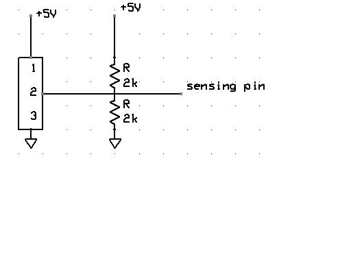
I'm interested in using an SPDT with center off (three-position toggle switch) to choose between three modes. The one example I have for this involved using an analog input on a Microchip microcontroller (I've attached the schematic below) and the pin would sense 5V, 2.5V, or 0V. How can I implement the same functionality (toggling between three modes) on a BS2, preferably without any additional ICs and as compactly as possible.
Thank you,
Phil

512 x 384 - 9K
512 x 384 - 11K
Comments
http://64.233.161.104/search?q=cache:mfH36R6QIF4J:www.parallax.com/dl/docs/cols/nv/vol1/col/nv23.pdf+SPDT+switch+and+BASIC+Stamp&hl=en
I know that this link rather long, however, I basically went and did a search on www.google.com for "SPDT switch and BASIC Stamp" and found this information.
Dave
▔▔▔▔▔▔▔▔▔▔▔▔▔▔▔▔▔▔▔▔▔▔▔▔
Dave Andreae
Tech Support
dandreae@parallax.com
Http://www.parallax.com
·
What I'm looking for is a combination of circuitry and code that will tell the stamp to be in one of three modes based on the position of a three position toggle switch.
Thank again,
Phil
As I remember Beau Schwabe has a method of obtaining a tri-state result from one pin port, which is essentially what you're looking to do with a SPDT C/O toggle switch. I'm sure as soon as he sees this thread, he will chime in. I THINK it was done with RCTIME and a resistor divider network, but don't hold me to that.
Perhaps Parallax might donate a small corner of their excellent web site (say "Parallax Tech Reps - Tech Notes") for the very helpful general applications notes, and schematics that Beau used to keep on his own web site when he had it. That was a WEALTH of Stamp and analog information. Beau had/has circuits for lots of things which seemed like they couldn't be done, or couldn't be done easily.
I'd be willing to bet there are other Parallax Tech Reps who might well have their own hidden trove of innovative Stamp tricks and circuity tricks which fall out of the ordinary scope of documented Stamp Applications. Some of us would just love to raid John B's hard drive for "super-circuits" some time
Regards,
Bruce Bates
▔▔▔▔▔▔▔▔▔▔▔▔▔▔▔▔▔▔▔▔▔▔▔▔
Beau Schwabe
IC Layout Engineer
Parallax, Inc.
After digging...· my solution for "obtaining a tri-state result from one pin port" was going from the stamp.· I think what Phil is looking for needs to go to the stamp.
There are certainly other ways to do this, but I think that the RCTIME approach would be the best solution for least amount of·I/O pins.
This subject has not really·been brought up.· The "web-page" died because of problems I was having with my service provider at the time.· After many attempts to
revive the web site, it was just never the same due to the number of broken links other people had (and still have) that point to my old sight.
Bruce and all that remember,
Here is the sight as you might remember it...
http://webpages.charter.net/schwabelove/BasicStamp/
Phil,
Check out the 3x5 keypad·as an alternate·solution for what you want to do.
▔▔▔▔▔▔▔▔▔▔▔▔▔▔▔▔▔▔▔▔▔▔▔▔
Beau Schwabe
IC Layout Engineer
Parallax, Inc.
Post Edited (Beau Schwabe (Parallax)) : 8/14/2005 9:32:51 PM GMT
Thanks,
Phil
With that bit of background, ( The Help file does a much better job of explaining RCTIME ) The switch is not correctly drawn, just recognize that in the center (off) position, the capacitor discharges only through R1 with the switch in the A or B position will place R2 or R3 in parallel with R1. Which will decrease the resistance through which C1 discharges and reduce the time stored in Variable.
Suggestion. Start with just R1 and C1 experiment with different values to understand how the command works. Then install the switch and the additional resistors. None of the resistor values are critical, you just need to be able to reliably differentiate between the two states. Good Luck and Happy Stamping.
·I can't open my attachment, I hope you can.
Post Edited (Philip Gamblin) : 8/15/2005 4:43:55 AM GMT
Thanks,
Phil
Do you mean to not connect the center/off pin to anything, or should it be connected to ground?
These are the switches I'm considering:
RTE Series Miniature Rotary Switches
3 position selector, 4 x 7.5 mm shaft, silver plating, Digikey p/n 401-1028-ND, $2.05, RTE0301N01
3 position selector, button actuator, silver plating, Digikey p/n 401-1029-ND, $2.05, R0302N01
http://dkc3.digikey.com/PDF/T052/1200.pdf
Thanks,
Phil
Thanks,
Phil