Using PULSIN to measure sound
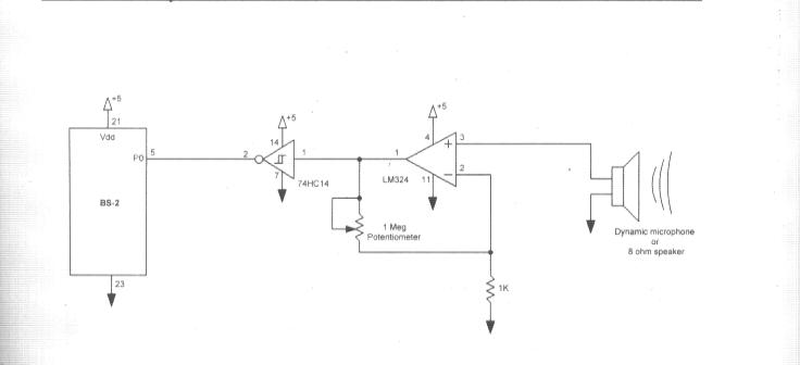
I'm experimenting with something I found in "The Microcontroller Application Cookbook", for "measuring the frequency of an external audio source".
I've attached the scehmatic. There's a couple of things I wonder:
1. Could the +5 Volts that goes into the 74C14 at pin 14 be taken from the BS2's Board of Ed. power rail? Or should it have it's own +5 Volt source?
*Also, if you look at the schem. you see what looks like a speaker, and it's stated there "Dynamic Microphone or 8 Ohm speaker", why would there be an 8 Ohm speaker there if you are measuring sound?
Is my code right?
pulse VAR Word
Main:
PULSIN 7, 1, pulse
pulse = pulse * 2 ' double the pulse width
DEBUG HOME
DEBUG "pulse = ", DEC5 pulse, " ", CR
GOTO Main
Thanks for any help, I appreciate it.
Tony
Post Edited (TonyA) : 8/13/2005 6:26:45 PM GMT


Comments
·· Yes, you can take the +5V source from the Vdd output on the BOE.· The 8 ohm speaker is being used as a poor-man's microphone, hence the op-amp.· As for you code, I didn't check it.· Is there a problem with the program and/or hardware?
▔▔▔▔▔▔▔▔▔▔▔▔▔▔▔▔▔▔▔▔▔▔▔▔
Chris Savage
Parallax Tech Support
csavage@parallax.com
Thank you. yeah, I don't get a reading for the frequency. I tried using a mic and then a line level (electronic keyboard to a 1/4" jack). I think with the line level input I would have to do some math?
I'm using the op amp and the Schmitt-trigger, I think it's wired correctly. To test it (the op amp and schmitt trigger circuit) I ran electric keyboard through the input, and the output (pin 2 of the schmitt trigger into an amplifier and I got sound out of it, then added pin 2 of the S-T to the BS2.) But, I don't get any values on my debug.
Thanks for any suggestions.
Tony
·· I couldn't find that circuit until I realized you listed the·first book.· The project is actually in the Second book, and everything seems to match that assuming you're input goes to P7.· I would re-check your wiring.· For anyone else interested, the circuit is on page·91 of the Microcontroller Application Cookbook Volume 2.
▔▔▔▔▔▔▔▔▔▔▔▔▔▔▔▔▔▔▔▔▔▔▔▔
Chris Savage
Parallax Tech Support
csavage@parallax.com