

BS2 Schematic
 knightofoldcode
Posts: 233
knightofoldcode
Posts: 233
Board,
I'm looking for a schematic, (if it exists) of the BS2's Pic and supporting components to make the pic run. No other components, specifically not the RS-232 circuitry for programming.
I want to build in a BS2 interpreter chip (http://www.parallax.com/detail.asp?product_id=PBASIC2C/P) into a PCB, and won't need to be able to program from within that board. I'd simply remove the EEProm and program elsewhere then re-insert into end PCB.
Does anyone have this schematic?
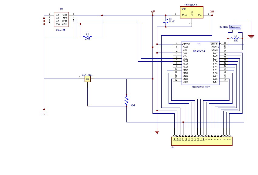
I have included a schematic with this post. I took the schematic produced by Parallax for the BS2 OEM and removed what I suspcted was all of the rs-232 circuitry from it. Can someone look at that new schematic and see if I have it correct? Specifically the "new" R4, I think this is needed, but not certain.
Value of R4 is 10K.
Much, Much, Thanx in advance!
Knight.
I'm looking for a schematic, (if it exists) of the BS2's Pic and supporting components to make the pic run. No other components, specifically not the RS-232 circuitry for programming.
I want to build in a BS2 interpreter chip (http://www.parallax.com/detail.asp?product_id=PBASIC2C/P) into a PCB, and won't need to be able to program from within that board. I'd simply remove the EEProm and program elsewhere then re-insert into end PCB.
Does anyone have this schematic?
I have included a schematic with this post. I took the schematic produced by Parallax for the BS2 OEM and removed what I suspcted was all of the rs-232 circuitry from it. Can someone look at that new schematic and see if I have it correct? Specifically the "new" R4, I think this is needed, but not certain.
Value of R4 is 10K.
Much, Much, Thanx in advance!
Knight.
851 x 579 - 63K
Comments
Chris I.
http://www.parallax.com/html_pages/downloads/basicstamps/documentation_basic_stamp.asp
▔▔▔▔▔▔▔▔▔▔▔▔▔▔▔▔▔▔▔▔▔▔▔▔
Jon Williams
Applications Engineer, Parallax
·· Is R4 being pulled high?· You have no symbol there to indicate where the line ties to.
▔▔▔▔▔▔▔▔▔▔▔▔▔▔▔▔▔▔▔▔▔▔▔▔
Chris Savage
Parallax Tech Support
csavage@parallax.com
Yeah, it's pulled high, to VDD, it's on the schematic. [noparse]:)[/noparse]
·· At my resolution, unless I expand the image to full size, it cuts out much of the drawing.· Kind of like AcroReader does.·
▔▔▔▔▔▔▔▔▔▔▔▔▔▔▔▔▔▔▔▔▔▔▔▔
Chris Savage
Parallax Tech Support
csavage@parallax.com
Ah! n/p [noparse]:)[/noparse]
Jon,
Every schematic that I've ever seen come from Parallax has the RS-232 circuitry. I just checked all of the ones you mentioned to look at, and didn't find any that left out the RS-232 circuitry for programming. I just want enough circuitry to run the PIC and the EEProm, nothing else, I don't need to be capable of programming the EEProm from this board, I'll pull out the EEProm and program it inside of a different board, tehn pop it into this one. (This way I save a couple bucks, but mostly I save the PCB space in the final product, should be around 10 boards, all the same)
Chris,
I'm not going to leave out the brownout detector. It's cheap insurance. That way the operator of the final prodcut doesn't freak when weird stuff happens, just the power will go out instaed of all kinds of other weird stuff.
Knight.
The MN13811 reset circuit has open drain output, and therefore does in fact require the pullup resistor you already included at R4. The MN138xxx is a whole series of parts. You also need a suffix on the end to specify the voltage. MN13811-R for reset at 4.1 volts. -S for reset at 4.3 volts. If you use the plain MN1381-R, it has a CMOS output instead of open drain, and then you coulld dispense with R4.
I'm pretty sure you know this already, but the PIC16C57 in the SSOP package on the BS2-IC module has a different pinout than the same chip in the DIP package.
▔▔▔▔▔▔▔▔▔▔▔▔▔▔▔▔▔▔▔▔▔▔▔▔
Tracy Allen
www.emesystems.com
▔▔▔▔▔▔▔▔▔▔▔▔▔▔▔▔▔▔▔▔▔▔▔▔
Chris Savage
Parallax Tech Support
csavage@parallax.com
Did you use PCBExpress? If so, let me get the layout! [noparse]:)[/noparse]
Knight.
Nope, didn't know it had a differnt pinout, however, luckily, I'm not going to use the SSOP package in my final product, just the DIP package, but thanks for the warning! [noparse]:)[/noparse]
I hadn't even thought about the fact that I left those pins floating! I'll pull pins ra2 and ra3 high with a 10k resistor.
And speaking of the MN13811, does anyone know where to get this? Mouser doesn't seem to ahve it anymore, and Digikey says it's a 1000 minimum, obsolete unit. Does Parallax sell it, like they do with the Crystal, Pic, and EEProm? I didn't see it anywhere on the page, even though in the BOM it lists the Parallax p/n of 603-00002. If I can't seem to find a supplier I might have to use Chris's method and simply leave it out (and obviously getting rid of R4). (Not pull it high, I want to keep my reset button.)
·· Just for clarification, tying a line·high and pulling a line·high are two different things.· I would recommend pulling lines·high in this situation.· You would still be able to force them LOW, should you need to.
▔▔▔▔▔▔▔▔▔▔▔▔▔▔▔▔▔▔▔▔▔▔▔▔
Chris Savage
Parallax Tech Support
csavage@parallax.com
I used EaglePCB.· I'm reluctant to share anything before I test the boards.· Also, there is some proprietary information on the boards as well.
Chris,
To jog your memory, it was me you helped last week.
Chris I.
·· I thought I went through this with someone.· Yeah, I think I replied that the schematic gives you the clues you need to know what to do with those lines.·
▔▔▔▔▔▔▔▔▔▔▔▔▔▔▔▔▔▔▔▔▔▔▔▔
Chris Savage
Parallax Tech Support
csavage@parallax.com
I'm familiar with the differences, is there any point at which it seemed I wasn't?
I looked over my posts and didn't see any point at which I thought I had confused the two. But, I've been know to say one thing and mean another. [noparse]:)[/noparse]
I'm extremly proficient with firearms, particularly long range rifles. (Sniper.) And I will commonly say a clip instead of magazine, yet they are two DIFFERNT things. (Clip is a Stripper clip, and only holds the round around teh base, or the rim. However a magazine fully enclosues all of the rounds, and doesn't leave them exposed to the outside, except on the top.) So, if I said tying it high instead of pulling it high, it may have just been a slip up.
Knight.
·· The section where you wrote:
Specifically that last statement...··
▔▔▔▔▔▔▔▔▔▔▔▔▔▔▔▔▔▔▔▔▔▔▔▔
Chris Savage
Parallax Tech Support
csavage@parallax.com
I said that in response to the other Chris's comment. [noparse]:)[/noparse]
Knight.