PWM controlled current source
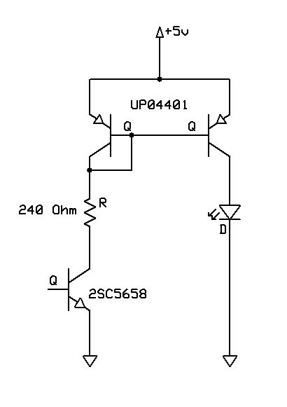
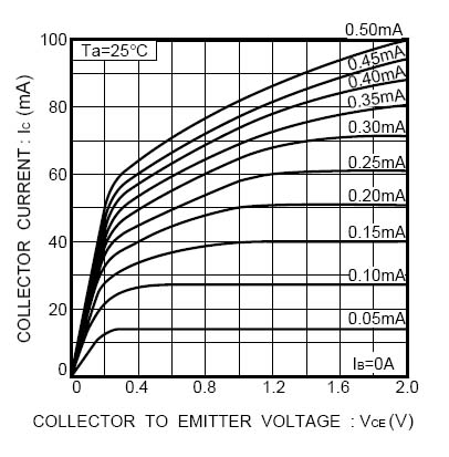
I need to illuminate a white LED backlight, the specifications only give that the bias current should be 15mA. No value for the voltage drop Vf of the LED is given. So the standard method using·a bias resistor is out of the question. Im thinking the easiest way of doing this is using a current mirror, but since I need on-off control I need a chopping transistor. The circuit I came up with is below, it consists of a matched pair pnp current mirror, a current setting resistor and a npn transistor to control the operation of the mirror. The Vbe for both the npn and pnps are ~ 0.7V so Ir = (5 - 1.4)/240 = 15 mA. I understand that Ir is only an approximation of Id, but the sum of Ib's is ~ 150 uA so it's a close approximation. My question is: I understand safe practice is to place a resistor between the output pin and the base of the npn resistor, but assume I don't. Ic of the npn is limited to 15mA, this indicates an Ib of 50uA and Vbe(max) = 7V, so if Vbe = 5V, Ib should still be 50uA and the npn will be in deep saturation. Am I correct on my understanding of the circuit?
I have also included the transfer curve for the npn. Also, am I correct at believing this circuit should be able to handle a Vf of the LED·upto 4.3V?
Post Edited (Paul Baker) : 7/1/2005 3:19:07 PM GMT
I have also included the transfer curve for the npn. Also, am I correct at believing this circuit should be able to handle a Vf of the LED·upto 4.3V?
Post Edited (Paul Baker) : 7/1/2005 3:19:07 PM GMT


Comments
Seems to me the simplest thing to do would be power the backlight with a bench supply, start at zero and turn up the voltage until the current hits the 'elbow' (make sure the supply has an appropriate current limit set) and then you have Vf.· At this point use the appropriate resistor to get the propper current for your supply voltage and Vf of the LED.
Nate
BTW the calculation of the above R is wrong the voltage drop due to the npn is Vce(sat) which is ~ 0.09 V so R should be 280 Ω.
Post Edited (Paul Baker) : 7/1/2005 3:48:31 PM GMT
·· Ya beat me to it...Given a current spec, and no forward voltage, that's exactly when I do.· then I calculate using the drop, and pick the appropriate resistor.· If there's no exact match, I go to the next highest standard value.
▔▔▔▔▔▔▔▔▔▔▔▔▔▔▔▔▔▔▔▔▔▔▔▔
Chris Savage
Parallax Tech Support
csavage@parallax.com
Post Edited (Paul Baker) : 7/1/2005 5:10:49 PM GMT
"Ha Shi" - analog guru ?··I usually consider your opinions to outweigh mine most of the time.· ...but thanks for the comp.
Can't you use the "diode check" on a DMM to get Vf of your LED?·· Has worked for me several times.
For a couple of LED's I have laying around here...
WHITE = 2.73 Vf
RED = 1.66 Vf
GREEN = 1.83 Vf
IR LED = 1 Vf
▔▔▔▔▔▔▔▔▔▔▔▔▔▔▔▔▔▔▔▔▔▔▔▔
Beau Schwabe
IC Layout Engineer
Parallax, Inc.
Post Edited (Beau Schwabe (Parallax)) : 7/1/2005 7:25:13 PM GMT
Thanks everyone for thier insight,
Paul
▔▔▔▔▔▔▔▔▔▔▔▔▔▔▔▔▔▔▔▔▔▔▔▔
If so, I can dig out the results I got for mine. (3.9-4.2V seems familiar, but it was ages ago...)
If not, then The above tactics sound fine.
Steve
Post Edited (Paul Baker) : 7/1/2005 8:03:35 PM GMT
Got a couple more hours of work to do here first, though. Bah, Friday night, and I'm churning out VHDL for a crappy HDTV demo. Worse, my local pub has a beer festival on - 50 beers, and I've only managed 8 so far this week [noparse]:([/noparse]
Steve
2mA @ 5.4V
5mA @ 6.1V
8mA @ 6.4V
10mA @ 6.5v
12mA @ 6.6V
15mA @ 6.7V
18mA @ 6.8V
all at 15 degrees C - LED curves do change with temperature.
(Damn - that should be 25 degrees), sorry.
It's a lovely little display - well worth persevering with.
(Yep, does look like 2 white diodes in series. Surprisingly bright, for so little power)
Hope that helps,
Steve
Post Edited (SteveW) : 7/1/2005 10:49:44 PM GMT
▔▔▔▔▔▔▔▔▔▔▔▔▔▔▔▔▔▔▔▔▔▔▔▔
Anyway, if need be, Maxim (and Linear, I think), make some pretty easy to integrate step-ups. Some even have I2C / SPI curent controls, if you need...
Steve
You indicated that you needed to vary the brightness by using a chopping method. Might that imply you have a couple of pins available from an SX by chance?
There is a really neat very simple buck-boost pulse width circuit that you can use to set the current you want. Best part is, it will generate output voltages lower than or greater than your input voltage. All done with a transistor switch (2N3904), two small inductors (1 mH or so) a small cap (.01) and a diode (1N4448). By adusting the switch ON duration and the ON/OFF duty cycle, you can get out whatever you want from (almost) any input you have, even 1.5Volts!
If this is interesting, then let us know, and I'll post the details.
Happy experimenting,
Peter (pjv)
▔▔▔▔▔▔▔▔▔▔▔▔▔▔▔▔▔▔▔▔▔▔▔▔