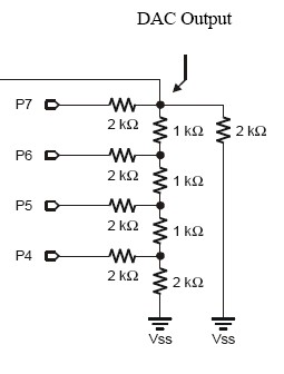
R-2R resistive Ladder
Dear Sir :
···············
In Stamp In Class => Basic analog and digital Chapter 4
···············
Because My background is mechanical engineering
so I can not understand why
·P7 = 1 , P6 = 1, P5 = 1, P4 = 1 then DAC output will be 3 volts
P7 = 1 , P6 = 0, P5 = 1, P4 = 1 then DAC output will be 2.25 volts
Could you give me a·complete explanation
Thanks for your help
Hsiaochung Liu
hsiaochung@cc.chit.edu.tw
···············
In Stamp In Class => Basic analog and digital Chapter 4
···············
Because My background is mechanical engineering
so I can not understand why
·P7 = 1 , P6 = 1, P5 = 1, P4 = 1 then DAC output will be 3 volts
P7 = 1 , P6 = 0, P5 = 1, P4 = 1 then DAC output will be 2.25 volts
Could you give me a·complete explanation
Thanks for your help
Hsiaochung Liu
hsiaochung@cc.chit.edu.tw


Comments
Start by looking at Figure 4.6 in Basic Analog and Digital.· It shows the 16 different combinations that OUTB can send to the resistor ladder circuit·(commonly referred to as an R2R ladder). Each 0 corresponds to a low signal, and each 1 corresponds to a high signal. For example, the code:
· OUTB = %1001
· DIRB = %1111
is the same as
· HIGH 7
· LOW 6
· LOW 5
· HIGH 4
In this particular case, 5 V will be applied to P7 and P4, and 0 V will be applied to P5 and P6. By applying these voltages to the R2R ladder, the resulting voltage divider turns out to be 1.84 V. The next binary number in the series is %1011. Instead of LOW 4, we are now sending HIGH 4, and instead of 0 V, P4 now·sends 5 V to that R2R ladder input. The resulting voltage divider is now different, with the output at 2.04 V.
Looking deeper into why the voltages work out the way they do requires some practice with reducing series and parallel resistor networks down to voltage dividers. Most introductory electronics textbooks demonstrate examples and offer practice problems. Some of the building blocks are in a nice web site called www.play-hookey.com -> Electronic Theory: Direct Current. Look over Resistor Construction, Resistors in Series, Resistors in Parallel, and The Voltage Divider.
NOTE: Basic Analog and Digital is available for download from www.parallax.com -> Downloads -> Stamps in Class Tutorials.
Post Edited (Andy Lindsay (Parallax)) : 7/1/2005 5:21:51 PM GMT