

Spectrum Lighting Effect using Programmable Light Dimmer (ala RTurley)

Folks,
I thought that it might be useful to start a new thread for this, rather
than tacking it on the end of the excellent discussion RTurley started
("Controlling 120 VAC lights with a Stamp")..
There is a restaurant near my home that has the entire wall behind
the bar lit up with a bank of lights that shift through the colors
of the spectrum. This was sufficiently cool that I wanted something like
this for my house.
I figured that I could get every color of the spectrum, and alot
more, using just three colors (red, green, and blue)....after all, that's what
all those TVs out there do. Attachment 1 shows a plot of the RGB
values needed to reproduce the visible spectrium from 380 nm to 780nm.
( see http://www.isc.tamu.edu/~astro/color/spectra.html for the original
FORTRAN code (gasp!) and www.johnny-lin.com/py_code/wavelen2rgb.py
for the more modern Python code I used to get the RGB values).
Now I just needed a way to control some bright lights....
All I needed to do was make a 3-channel dimmer. And RTurley had lighted the
way. Sorry. But his posting seemed like a good place to start.
I made some changes to RTurley's basic circuit. I was not concerned with
conserving output pins (since this would be a dedicated application),
so I removed the addressing scheme and used one Stamp output
line per latch. I assigned P0, P1, and P2 to R, G, and B, respectively.
P3 and P4 are the serial data and clock for the shift register.
Not being the trusting type, I wired-up one channel of the circuit on my
INEX-1000 board, and used the code (a heavily modified version of
RTurley's code (thanks RTurley!) in Attachement 2 to test it. And,
of course, it worked as advertised. The exact value at which the light
shuts off is a function of the resistor values used, so the code will
need to be adjusted for your particular parts.
I used PCB123 (pcb123.com) to capture the
schematic and create the layout for the circuit. While I've made
and etched my own boards before, I decided to just bite the
bullet and pay to have several boards made...I figured that I could
always give them to my friends.
This is the relevant code fragment used to ramp from violet to
red:
Attachment 3 is the entire code I used to sweep through the spectrum and
back again., including all the RGB values in DATA statements. Not
complicated, but it sure looks cool using three rope-lights twisted together
to "mix" the colors....
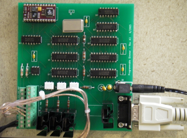
Attachment 4 is a picture of the board itself.
Many thanks to RTurley for his initial posting.
croussi
I thought that it might be useful to start a new thread for this, rather
than tacking it on the end of the excellent discussion RTurley started
("Controlling 120 VAC lights with a Stamp")..
There is a restaurant near my home that has the entire wall behind
the bar lit up with a bank of lights that shift through the colors
of the spectrum. This was sufficiently cool that I wanted something like
this for my house.
I figured that I could get every color of the spectrum, and alot
more, using just three colors (red, green, and blue)....after all, that's what
all those TVs out there do.
Attachment 1 shows a plot of the RGBvalues needed to reproduce the visible spectrium from 380 nm to 780nm.
( see http://www.isc.tamu.edu/~astro/color/spectra.html for the original
FORTRAN code (gasp!) and www.johnny-lin.com/py_code/wavelen2rgb.py
for the more modern Python code I used to get the RGB values).
Now I just needed a way to control some bright lights....
All I needed to do was make a 3-channel dimmer. And RTurley had lighted the
way. Sorry. But his posting seemed like a good place to start.
I made some changes to RTurley's basic circuit. I was not concerned with
conserving output pins (since this would be a dedicated application),
so I removed the addressing scheme and used one Stamp output
line per latch. I assigned P0, P1, and P2 to R, G, and B, respectively.
P3 and P4 are the serial data and clock for the shift register.
Not being the trusting type, I wired-up one channel of the circuit on my
INEX-1000 board, and used the code (a heavily modified version of
RTurley's code (thanks RTurley!) in Attachement 2 to test it. And,
of course, it worked as advertised. The exact value at which the light
shuts off is a function of the resistor values used, so the code will
need to be adjusted for your particular parts.
I used PCB123 (pcb123.com) to capture the
schematic and create the layout for the circuit. While I've made
and etched my own boards before, I decided to just bite the
bullet and pay to have several boards made...I figured that I could
always give them to my friends.
This is the relevant code fragment used to ramp from violet to
red:
addr = RGBspectrum     ' the ordered (RGB) triples that make up the spectrum
DEBUG CR,"ramping up",CR,CR
FOR i = 1 TO 270   ' the number of RGB values in the spectrum
  READ addr, R
  READ addr+1, G
  READ addr+2, B
  DEBUG DEC i, " ", DEC R, " ", DEC G, " ", DEC B,CR

  ' get the inverse, since 200 is "off", and 0 is "on"
  R = 200 - R
  G = 200 - G
  B = 200 - B

  ' send the R-channel
  DeviceAddr = RedTriac
  TriacVal = R
  GOSUB SendTriac

  ' send the G-channel
  DeviceAddr = GreenTriac
  TriacVal = G
  GOSUB SendTriac

  ' send the B-channel
  DeviceAddr = BlueTriac
  TriacVal = B
  GOSUB SendTriac

  addr = addr + 3       'get to the next color
  'PAUSE 5

NEXT
Attachment 3 is the entire code I used to sweep through the spectrum and
back again., including all the RGB values in DATA statements. Not
complicated, but it sure looks cool using three rope-lights twisted together
to "mix" the colors....
Attachment 4 is a picture of the board itself.
Many thanks to RTurley for his initial posting.
croussi
467 x 322 - 5K

640 x 474 - 252K
Comments
How much did it cost to have the board(s) done at pcb123? I have tried expresspcb, and they worked well but without the silkscreen, or the soldermask. (3 for 62$ total, at about 5" x 3" size)
Here is a DIY tri-color (R,B,G) LED controller with a serial interface:
http://home.mindspring.com/~phil.ray/smartLED/
Last month I posted a message about a tri-color LED controller chip on the main Stamp Forum, but I'll have to dig that out, to repost it here.
Regards,
Bruce Bates
I ordered 6 boards (a total of 22 sq. in. each) for $50 each. I wanted 2-3 of them for myself (indoors,
outdoors, etc.), and figured I find some way to get rid of the others.... they would have been cheaper
without the silkscreen and soldermask.
CJR