

MOSFET switching for power conservation
 daviddrake
Posts: 20
daviddrake
Posts: 20
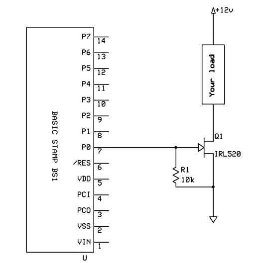
This concerns the application of a MOSFET, similar to the BS170 or IRL520 used to gate the power supply for a sensor system. This is intended to allow the sensor to be powered for very brief periods of time to conserve battery power. There are several examples in the Forum that use the transistor and 10 K ohm resistor to switch the sensor (often a Ping) to ground. The typical circuit looks like the (hopefully) attached image.
With a resistor from the Gate to the Source.
In a new application we are using a sensor that must use the
transistor "above " the load to control V+ and not the path to ground. It would be desirable to use a V+ of about 10 volts and use the output of a BS2pe to control the gate. The BS2pe would still be used with a Vdd of 5 volts. How would the components or circuit change to meet this need? I think I have seen a reference on this, but haven't located it.
Thanks!
David Drake
516 x 529 - 18K
Comments
Thanks for correcting me, ECO.
▔▔▔▔▔▔▔▔▔▔▔▔▔▔▔▔▔▔▔▔▔▔▔▔
Jon Williams
Applications Engineer, Parallax
Post Edited (Jon Williams (Parallax)) : 6/23/2005 4:48:54 PM GMT
·· Just out of curiosity, what is the sensor that you're trying to power from the 10 volts?
▔▔▔▔▔▔▔▔▔▔▔▔▔▔▔▔▔▔▔▔▔▔▔▔
Chris Savage
Parallax Tech Support
csavage@parallax.com
Sorry for you but the source follower is in this case a bad solution.
Assume the gate goes to 5v, the FET will go on, the load will gon on (10v),
the Vgs will be -5v, the FET will go off.
Regards
ECO
Alternatives are to use a voltage regulator that has a shutdown pin with logic threshold (e.g., the LT1121), or look at photomos relays, little dip packages that use an led input to an isolated mosfet output.
▔▔▔▔▔▔▔▔▔▔▔▔▔▔▔▔▔▔▔▔▔▔▔▔
Tracy Allen
www.emesystems.com
1. We are using the SensComp MINI series of sensors for sonic ranging. Longer range, good enviromental stability, a little pricier, but well worth it. This also points the way to a variety of high power sensors.
2. We bypassed the on board regulator on the MINI and fed it with Vdd, with pulse power from a 3300 uf cap. So we could keep to a common supply voltage.
3. We used high side switching with a 5305 - high power PMOS device. Very low effective serial resistance. The MINI was then always grounded.
4. We used a 5 k ohm resistor from an output pin to the PMOS gate, with 1uf cap to ground for stability during "sleep" glitches.
5. Flawless operation.
Key findings -
1. Low on resistance of the PMOS transistor is critical.
2. PMOS high side switching is fine. See page 153 of Gilliland's Cookbook 2 .
3. Use of a common supply voltage reduces complexity, but be sure to use a large enough cap for peak current supply.
4. Operation was excellent.