

To Resist or Not To Resist
 Jesse Massey
Posts: 39
Jesse Massey
Posts: 39
Hello,
Well I am on my·newest project with the SX28AC, this time I am building a controller for a Genie Lift. The old one fried and cost a lot to replace so I figured I could build a new one for cheap with a SX.
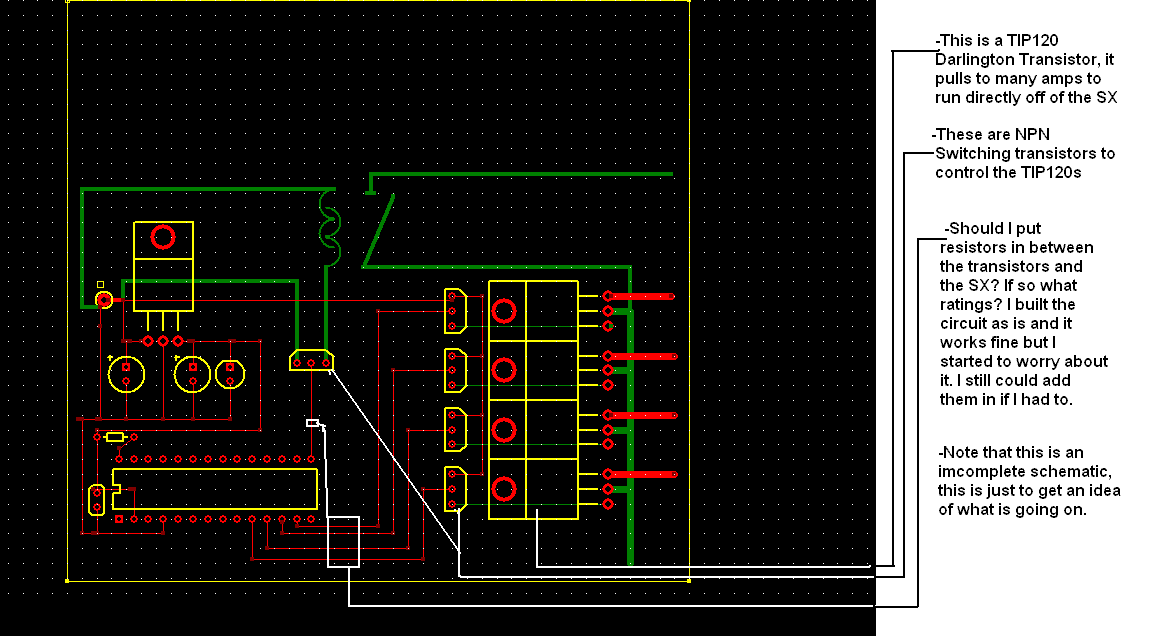
I am using the SX to switch four hydraulic valves on and off, and to switch a motor on and off. The valves require about 1 amp at 24 VDC to open them. To drive the hydro valves I am using a TIP120 Darlington Transistor, the TIP120s are driven by a NPN switching Transistor, and finaly the switching transistor is driven by the SX chip.
The motor is switched on and off with a large solenoid(think automotive style), this solenoid is driven by a smaller solenoid and it is driven by a NPN switching transistor.
Anyway I figured I would pass this by you guys and see what you think. As you can see I don't know a lot about hardware, I have always focused on software side of things but this project was presented to me and I have to do it.
Here is an incomplete·schematic of it. I have hooked it up but have yet to test it with a real load.
thanks,
Jesse
Well I am on my·newest project with the SX28AC, this time I am building a controller for a Genie Lift. The old one fried and cost a lot to replace so I figured I could build a new one for cheap with a SX.
I am using the SX to switch four hydraulic valves on and off, and to switch a motor on and off. The valves require about 1 amp at 24 VDC to open them. To drive the hydro valves I am using a TIP120 Darlington Transistor, the TIP120s are driven by a NPN switching Transistor, and finaly the switching transistor is driven by the SX chip.
The motor is switched on and off with a large solenoid(think automotive style), this solenoid is driven by a smaller solenoid and it is driven by a NPN switching transistor.
Anyway I figured I would pass this by you guys and see what you think. As you can see I don't know a lot about hardware, I have always focused on software side of things but this project was presented to me and I have to do it.
Here is an incomplete·schematic of it. I have hooked it up but have yet to test it with a real load.
thanks,
Jesse
bmp
363K
Comments
·· To answer the question in the pic, yes you should definately put resistors between the SX I/O pins and the transistor base.· You can use any value from 220 ohms to 1K without issue.· I myself use 1K, but as I said, with 5 volts going to the TIP120's you should be alright.· And you're correct, they draw, I believe about·120mA straight up on the base.· Good luck with this project.
P.S. - Resistance is futile!
▔▔▔▔▔▔▔▔▔▔▔▔▔▔▔▔▔▔▔▔▔▔▔▔
Chris Savage
Parallax Tech Support
csavage@parallax.com
Post Edited (Chris Savage (Parallax)) : 6/10/2005 5:54:04 PM GMT
I would also make the traces from the TIP 120s as big as you can. An amp of current isn't that huge, but it's still a substantial amount. When I design PCBs, the last thing I do after the the layout is complete is to go back and increase the trace size wherever possible. For traces that carry power and ground, I typically use 40 to 50 mil wide traces.
You've already made them pretty big, but you still have room for even bigger traces. Remember, the traces can be wider than the pads they connect to.
Thanks, PeterM
I agree with Chris - you need the serial resistors - they limit the current that flows from the SX outputs (when high) into the bases of the driver transistors.
I'm not sure what transistor types you use to drive the TIP120s, so I can't tell if these drivers invert the logic, i.e. if the TIPs will conduct, (i.e. the solenoids will be activated) when the SX pin is at low level, or has high impedance. This might cause dangerous situations.
As you know, all SX port pins are configured as inputs (having high impedance) on reset or power-on. With an inverting driver, this would mean that all solenoids would be activated whenever the SX is in reset state, or when it is "running wild" by some reason, leaving the port pins at high-Z (inputs). Therefore, such circuits should always be designed in a way that makes sure that solenoids, relays, etc. will only get activated with a high level at the driver inputs. You could simply pull the SX out of its socket (I assume it has one
In one of my SX-based projects, I had to PWM-control the speeds of DC motors, each of them rated at 24 Volts, 10 Amps max. For this project, I used IGBTs (Isolated Gate Bipolar Transistors) to drive the motors. The nice feature of IGBTs is that they have a relatively high input impedance, similar to FETs (i.e. low input power), combined with the low Uce saturation voltage of bipolar transistors when "turned on". I have attached a modified schematic of my project, showing how the IGBT could drive a solenoid instead of a motor. The IRG4PC40KD I'm using can handle up to 600 Volts with a collector current of up to 25 Amps, a saturation Uce of 2.1 Volts at a gate-emitter voltage of 15V.
The schematic shows a driver circuit with a 2N3906 and a 2N3904. I'm using two transistors to make sure that the IGBT only conducts when the SX output is at high level (see above). The IGBT I'm using requires about 15 Volts at the gate to get "turned on". As the maximum allowed gate-to-emitter voltage for this type is 20 Volts, I'm using the 1.5K and 1K resistors to limit that gate voltage.
Please also note the diode in parallel to the solenoid. This diode should be a fast switching diode, capable to short the reverse current generated by the solenoid when being turned off. Without such a diode, the IGBT (or any other driver transistor) might be killed. As you can see, this IGBT has a "built-in" recovery diode but this can't kill the solenoid's reverse current, it is only useful when the IGBT is used in bridge configurations.
This type of IGBT would definitely be an "overkill" for your application (maybe not for the "large" solenoid you had mentioned), but there are other types available from various manufacturers that can be directly controlled from an SX output pin, i.e. which are "turned on" with 5 Volts Uge.
▔▔▔▔▔▔▔▔▔▔▔▔▔▔▔▔▔▔▔▔▔▔▔▔
Greetings from Germany,
G
I absolutely agree - on my motor control PCB, the trace size is about 8mm for the power traces, and the traces are 70µm thick instead of 35µm, which is the standard. If possible, I try to keep such "power traces" on one side of the board. When there is no other way than "switching sides" I let the traces overlap on both sides far enough to allow for a bunch of additional vias between both sides.
▔▔▔▔▔▔▔▔▔▔▔▔▔▔▔▔▔▔▔▔▔▔▔▔
Greetings from Germany,
Günther
·· You bring up a very good point...If you use an NPN (such as 2N3904) transistor to drive the TIP120's, in it's normal configuration the base would have to be LOW to trigger the TIP120, and HIGH to turn them off.· I didn't even catch that.
▔▔▔▔▔▔▔▔▔▔▔▔▔▔▔▔▔▔▔▔▔▔▔▔
Chris Savage
Parallax Tech Support
csavage@parallax.com