

Buyer Beware
 KenM
Posts: 657
KenM
Posts: 657
"Buyer Beware"
In the BS2 forum, a link was posted (included below) explaining use of a diode across a relay coil.
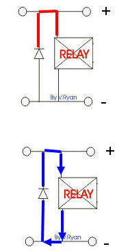
The link refered to indicates the diode protects the relay/circuit from a spike when the relay turns off.....which it does.
But not as the shown indicated by the RED line and explained in the original picture.
In reality, when the relay coil is de-energized the spike produced by the relay coil takes a path indicated in blue for the attachment named REAL and current is allowed to pass through the coil and diode....not blocked by the diode when the coil turns off.
Why this happens might be too deep and off topic for the Stamp section. I will move this post to the sandbox.
トヨタは すばらし です!!
Post Edited (KenM) : 5/15/2005 5:50:55 PM GMT
In the BS2 forum, a link was posted (included below) explaining use of a diode across a relay coil.
The link refered to indicates the diode protects the relay/circuit from a spike when the relay turns off.....which it does.
But not as the shown indicated by the RED line and explained in the original picture.
In reality, when the relay coil is de-energized the spike produced by the relay coil takes a path indicated in blue for the attachment named REAL and current is allowed to pass through the coil and diode....not blocked by the diode when the coil turns off.
Why this happens might be too deep and off topic for the Stamp section. I will move this post to the sandbox.
▔▔▔▔▔▔▔▔▔▔▔▔▔▔▔▔▔▔▔▔▔▔▔▔pvallada said...
Are you using a diode to protect you from the relay's voltage spike when turning them off?
There's a simple diagram here:
http://www.technologystudent.com/elec1/diode1.htm
トヨタは すばらし です!!
Post Edited (KenM) : 5/15/2005 5:50:55 PM GMT
190 x 366 - 11K
Comments
-dave
▔▔▔▔▔▔▔▔▔▔▔▔▔▔▔▔▔▔▔▔▔▔▔▔
This is not a sig. This is a duck. Quack.
...those that would find the explanation 'too deep', and not be worried about the science behind it, they couldn't go wrong by just putting the diode in as shown on the diagram.
▔▔▔▔▔▔▔▔▔▔▔▔▔▔▔▔▔▔▔▔▔▔▔▔
·
Steve
http://ca.geocities.com/steve.brady@rogers.com/index.html
"Inside each and every one of us is our one, true authentic swing. Something we was born with. Something that's ours and ours alone. Something that can't be learned... something that's got to be remembered."
The concept was correct, just the explanation was a little off base, and I completly agree with your position of
"those that would find the explanation 'too deep', and not be worried about the science behind it, they couldn't go wrong by just putting the diode in as shown on the diagram."
With one·anal point that even I am guilty of......the diagram does not show which lead is positive. But viewing the diagram as "conventionally drawn" the positive is at the top of the picture.....
So I reposted the pic with polarity.
▔▔▔▔▔▔▔▔▔▔▔▔▔▔▔▔▔▔▔▔▔▔▔▔
トヨタは すばらし です!!
Post Edited (KenM) : 5/15/2005 5:48:04 PM GMT
If it were reversed, the current would flow thru the diode instead of thu the relay.
73
spence
k4kep
Yes the diode is shown correctly. It is the explanation and graphic illustration·that is incorrect.
▔▔▔▔▔▔▔▔▔▔▔▔▔▔▔▔▔▔▔▔▔▔▔▔
トヨタは すばらし です!!
·· I think I missed something...What/where was something posted wrong?
▔▔▔▔▔▔▔▔▔▔▔▔▔▔▔▔▔▔▔▔▔▔▔▔
Chris Savage
Parallax Tech Support
csavage@parallax.com
Somebody please educate me if my thinking is messed up......I believe the explanation at the link above is a little off when the author's animation of a spike gets "blocked" at the diode.....
Or am·I misinterpreting the animation?????
▔▔▔▔▔▔▔▔▔▔▔▔▔▔▔▔▔▔▔▔▔▔▔▔
トヨタは すばらし です!!
In electronics, we often get people that explain an operable circuit from more than one point of view. Eventually, someone gets really confused.
And then [noparse][[/noparse]as is the case here], someone else clairifies that the circuit really does work - it is one of the explanations that is poor, not the circuit
As long as electricty has polarity, we will have these communication breakdowns. Just consider if 'beginner's mind'.
▔▔▔▔▔▔▔▔▔▔▔▔▔▔▔▔▔▔▔▔▔▔▔▔
G. Herzog in Taiwan
I don't think you are misinterpreting and you are correct that the doide is not intended to "block" anything. When the magnetic field in the relay coil collapses, it generates a "counter-EMF" or flyback voltage and the diode is there to offer a lower resistance path than other "sensitive" things connected to it for this spike to follow.
Or have I missed something?...
▔▔▔▔▔▔▔▔▔▔▔▔▔▔▔▔▔▔▔▔▔▔▔▔
Truly Understand the Fundamentals and the Path will be so much easier...
My point exactly.....and I don't think you missed anything.
And Kramer....the circuit as shown at the web sight, I am quite certain the animation is wrong.
The science behind all of this is not necessarily important to the beginner, however, some time later down the road, the correct understanding of the operation should be known.
▔▔▔▔▔▔▔▔▔▔▔▔▔▔▔▔▔▔▔▔▔▔▔▔
トヨタは すばらし です!!