

Tachometer (think I need a little buffer help)
 Eric R
Posts: 225
Eric R
Posts: 225
After reading a post involving the 4N25 optocoupler I set out to give it a shot. I ran into an issue that I cannot resolve in the code.
PULSIN 13,1,hi
PULSIN 13,0,lo
pulsesum·=·hi + lo
rpm = (50000/pulsesum*10)+(50000//pulsesum*10/pulsesum)*15
This worked pretty good except it is very touchy and jumps around. I would like to see a more stable reading. Any ideas on how to buffer it a little or is there a better way to calculate this?
A little background, The distributor was a old GM HEI unit a friend had laying around. I fabbed a quick adapter to chuck it up in a electric drill. I also hooked up a little analog tach for reference. I assume the drill to be more stable than the BS2 reports and the analog tach seems to confirm this.
If someone else has gotten something like this to work please post a little code for comparison
720 x 415 - 40K
Comments
·· Wouldn't the COUNT instruction be a better choice for measuring RPMs?· See the example code at this page:
http://www.parallax.com/html_pages/robotics/machining/RPM_display.asp
·· You'll have to modify things for your setup, but I think this might work a bit better.
▔▔▔▔▔▔▔▔▔▔▔▔▔▔▔▔▔▔▔▔▔▔▔▔
Chris Savage
Parallax Tech Support
csavage@parallax.com
COUNT 13, 100, tenth
RPM = tenth * 600 / 4
This was no where close, Well within a 1000 at 5000 RPM. The best I could figure is that there are 4 pulses per revolution given what I know about these engines. The HEI has 8 poles but turns half speed·of the crankshaft·giving 4 poles per revolution. Maybe someone will see a potential problem with the code?·Otherwise pulsin works fairly well.
I have been looking for a way·to average the readings however there doesn't seem to be a instruction for this nor have I found a way to do this.
I really do not have a use for this project but it seems that the question of a automotive tachometer comes up on the board every once in a while and never seems to get solved. It would be nice·to get·some working code going for the few in need.
I think it was KenM that posted the opto, possibly he has a snippet of code?
bugg
▔▔▔▔▔▔▔▔▔▔▔▔▔▔▔▔▔▔▔▔▔▔▔▔
Boe-bot: $229
Toddler: $249
Learning Google is your friend: priceless
Even a small measuring error can multiply up something awful when the period is so small...
As for 'looks like'...
You first measure the period until a rising edge(I think. Haven't used PULSIN in a while), then a period until a falling edge?
Unfortunately, there's no way those two periods will be right after each other as the BS2 needs a little time to execute the instructions.
You'll therefore first measure the low state, then skip the high and the next low before measuring the high state.
This wouldn't matter if you could be certain of two things:
1. That all low(active) pulses are equal, and...
2. That the pulse givers are placed with the exact same distance between them.
(This doesn't matter that much with analog instruments or instruments that counts pulses for a short period)
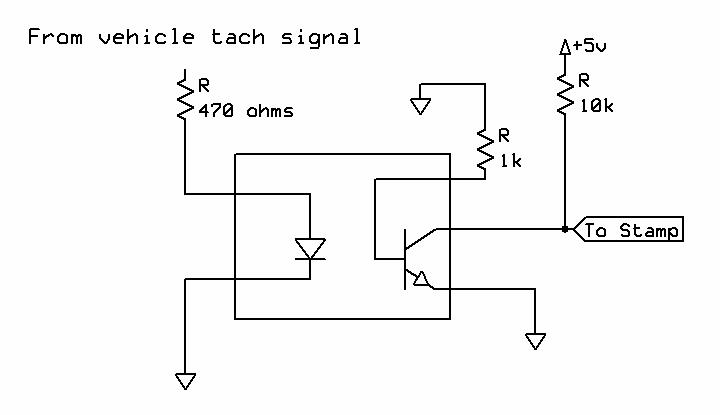
·· Since you have a scope, please post the period at low RPMs then at high RPMs.· We'll try to determine if Gadgetman's theory is correct based on that.· Also, I don't see where the schematic was posted by Ken, however, I am curious why the 1K resistor from the base to ground?· Ken?
▔▔▔▔▔▔▔▔▔▔▔▔▔▔▔▔▔▔▔▔▔▔▔▔
Chris Savage
Parallax Tech Support
csavage@parallax.com
bugg
▔▔▔▔▔▔▔▔▔▔▔▔▔▔▔▔▔▔▔▔▔▔▔▔
Boe-bot: $229
Toddler: $249
Learning Google is your friend: priceless
·· This is an opto-coupler...The base is driven by the LED.· The base pin I have used in the past to over-ride input, but never seen it pulled to ground, especially with such a low-value resistor.· This would seem to inhibit the LED signal, or at the very least attenuate it (Threshold).
▔▔▔▔▔▔▔▔▔▔▔▔▔▔▔▔▔▔▔▔▔▔▔▔
Chris Savage
Parallax Tech Support
csavage@parallax.com
▔▔▔▔▔▔▔▔▔▔▔▔▔▔▔▔▔▔▔▔▔▔▔▔
Jon Williams
Applications Engineer, Parallax
Dallas, TX· USA
·· I thought it might have something to do with attentuation, but I asked him to try disabling that resistor to see if it helps in his situation.· Without seeing a scope screenshot of the signal, and then what the output of the opto-coupler is putting out, I am not sure if that resistor is helping or hindering him.
Eric,
·· If you want to go through the extra trouble, maybe take a scope screenshot of the signal going to the stamp pin so we can see what it's doing with and without the resistor.
▔▔▔▔▔▔▔▔▔▔▔▔▔▔▔▔▔▔▔▔▔▔▔▔
Chris Savage
Parallax Tech Support
csavage@parallax.com
An appropriate value would be 68k or greater for a 4n25. The base resistor is not needed for the automotive application since the switching frequency is relatively low.
The purpose of the base resistor as shown is to speed up the turn off time. I never thought about using it as an override....
Post Edited (KenM) : 5/9/2005 7:21:58 PM GMT
·· Thanks for confirming this for me...One of the other Techs and myself were a bit confused, thinking such a small value would literally hold the base low.· Oh, and to answer your other question about over-ride.· When I used the opto in an automotive application once, I used optos to turn on certain functions based on input/feedback from the vehicle.· But for testing purposes (Read: Self-Test) the computer was able to activate the base through a resistor (I think 4.7K) to force the device on, hence over-ride the input being off.·
▔▔▔▔▔▔▔▔▔▔▔▔▔▔▔▔▔▔▔▔▔▔▔▔
Chris Savage
Parallax Tech Support
csavage@parallax.com
Post Edited (Chris Savage (Parallax)) : 5/11/2005 3:44:08 AM GMT
bugg
▔▔▔▔▔▔▔▔▔▔▔▔▔▔▔▔▔▔▔▔▔▔▔▔
Boe-bot: $229
Toddler: $249
Learning Google is your friend: priceless
Totally new to this forum but I have 2 cents to toss in. I had a scope on an old beetle yesterday, to see what signals are available. I have hopes of building an engine analyzer using the Stamp.
The signal I noted (measured at the coil as it goes into the distributor, therefore, essentially across the points, was a fair square wave with ringing at each transition. I am thinking that this should simply be cleaned up using a comparator or schmidt trigger, no? It has been quite a while since college and I have never designed with a schmidt, but from what I recall, they switch nicely on noisy signals. I was thinking that the noise might be causing the inconsistent numbers you are getting. Also, which digits are you finding unreliable? ie if you are measuring 2130 RPM and noting that the 3 & 0 are moving too much, then this might be a reality, depending on the engine. I read about a digital tach once which simply wired the last two digits to zero as the flashing made the whole display look unreliable, when in fact it was too accurate! An analog meter really only gives the 2 MSB, no, like we say it is idling at 800 or 825 (but how close is the "5")?
Rambling, but those are my thoughts. I am anxious to hear how you make out since I will be heading down this road shortly.
Looking forward to being a part of this forum. Thanks
Shawn