

RTCC Input
 Guenther Daubach
Posts: 1,321
Guenther Daubach
Posts: 1,321
Dear “SXers”
In one of my SX applications, all available I/O pins of the SX 28 were already dedicated to certain functions, when my customer had the idea that he needs a way to configure the system for a high or low baud rate at startup or reset with a jumper.
Usually, you would use one input pin to determine the status of that jumper (plugged or unplugged). As I said before, unfortunately, there was no more input pin available for that purpose.
The only unused input was the RTCC pin, and fortunately, one output pin was used to drive an LED, so an idea came up which I would like to share with you:
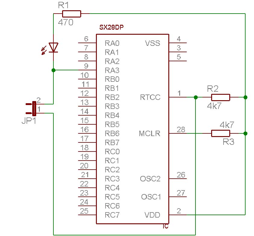
I wired the RTCC input as shown in the attached schematic (I have only drawn the components that are important for this text).
As you can see, the RTCC pin is pulled up via R2 to Vdd. When jumper JP1 is plugged, the pin is also connected to RA3, the output which drives the LED.
My idea was to set the OPTION register at program startup to let RTCC count the transitions at the RTCC pin, then toggle the LED on and off via RA3. In case JP1 is plugged, the RTCC pin would also be toggled, and RTCC should increment.
This is the first version of my code:
When testing the code with the debugger, RTCC did never increment, no matter if JP1 was plugged or not. I then tried to toggle ra.3 twice:
To my surprise, when stepping the code with the debugger, RTCC was incremented by one now. I then tried to run the program at full speed (50 MHz clock), setting a breakpoint on the test rtcc instruction. Again, RTCC was not incremented when JP1 was plugged.
Next I tried to reduce the clock frequency, assuming that the transitions on RA3 were too fast for the RTCC input, and – voila – it worked at 4 MHz clock. I then increased the clock frequency in steps, and found out that it worked up to 40 MHz.
In order to stretch the transitions, I added some NOPs as shown in the “final” code:
and it worked fine at 50 MHz clock. I finally tried to remove code for the second toggle, assuming that the debugger’s single step mode might cause the loss of the first transition but this was not the case. Running the code did not increment RTCC with one toggle either, so I activated the second toggle again. Seems as if the first transition on the RTCC pin gets lost by some reason.
Nevertheless, I have found a way to make use of the RTCC pin as a “spare input” for configuration purposes.
As you may guess, later in the program, the RTCC will be clocked from the system clock to generate the timing for ISR calls. Therefore, this method can only be used for getting some status information at startup, and when an output pin can be toggled without disturbing any external components connected to it.
▔▔▔▔▔▔▔▔▔▔▔▔▔▔▔▔▔▔▔▔▔▔▔▔
Greetings from Germany,
G
In one of my SX applications, all available I/O pins of the SX 28 were already dedicated to certain functions, when my customer had the idea that he needs a way to configure the system for a high or low baud rate at startup or reset with a jumper.
Usually, you would use one input pin to determine the status of that jumper (plugged or unplugged). As I said before, unfortunately, there was no more input pin available for that purpose.
The only unused input was the RTCC pin, and fortunately, one output pin was used to drive an LED, so an idea came up which I would like to share with you:
I wired the RTCC input as shown in the attached schematic (I have only drawn the components that are important for this text).
As you can see, the RTCC pin is pulled up via R2 to Vdd. When jumper JP1 is plugged, the pin is also connected to RA3, the output which drives the LED.
My idea was to set the OPTION register at program startup to let RTCC count the transitions at the RTCC pin, then toggle the LED on and off via RA3. In case JP1 is plugged, the RTCC pin would also be toggled, and RTCC should increment.
This is the first version of my code:
Main
    mov     !option, #%10111111   ; Let the RTCC pin trigger
                                  ; RTCC, no prescaler

    mode    MODE_DIR
    mov      !r, #%11110111

    clr     RTCC
    clrb      LowBaud           ; Flag indicating the baud rate
    clrb      ra.3              ; Toggle ra.3
    setb      ra.3
    test      rtcc              ; check if RTCC has been
    sz                        ; incremented
    setb      LowBaud
    ;
    ;.....
    ;
When testing the code with the debugger, RTCC did never increment, no matter if JP1 was plugged or not. I then tried to toggle ra.3 twice:
Main
    mov   !option, #%10111111 ; Let the RTCC pin trigger
                              ; RTCC, no prescaler

    mode    MODE_DIR
    mov      !r, #%11110111

    clr     RTCC
    clrb      LowBaud           ; Flag indicating the baud rate
    clrb      ra.3              ; Toggle ra.3
    setb      ra.3
    clrb      ra.3              ; Toggle ra.3 once more
    setb      ra.3
    test      rtcc              ; check if RTCC has been
    sz                        ; incremented
    setb      LowBaud
    ;
    ;.....
    ;
To my surprise, when stepping the code with the debugger, RTCC was incremented by one now. I then tried to run the program at full speed (50 MHz clock), setting a breakpoint on the test rtcc instruction. Again, RTCC was not incremented when JP1 was plugged.
Next I tried to reduce the clock frequency, assuming that the transitions on RA3 were too fast for the RTCC input, and – voila – it worked at 4 MHz clock. I then increased the clock frequency in steps, and found out that it worked up to 40 MHz.
In order to stretch the transitions, I added some NOPs as shown in the “final” code:
Main
    mov   !option, #%10111111 ; Let the RTCC pin trigger
                              ; RTCC, no prescaler

    mode    MODE_DIR
    mov      !r, #%11110111

    clr     RTCC
    clrb      LowBaud           ; Flag indicating the baud rate
    clrb      ra.3              ; Toggle ra.3
    nop
    setb      ra.3
    nop
    clrb      ra.3              ; Toggle ra.3 once more
    nop
    setb      ra.3
    nop
    test      rtcc              ; check if RTCC has been
    sz                        ; incremented
    setb      LowBaud
    ;
    ;.....
    ;
and it worked fine at 50 MHz clock. I finally tried to remove code for the second toggle, assuming that the debugger’s single step mode might cause the loss of the first transition but this was not the case. Running the code did not increment RTCC with one toggle either, so I activated the second toggle again. Seems as if the first transition on the RTCC pin gets lost by some reason.
Nevertheless, I have found a way to make use of the RTCC pin as a “spare input” for configuration purposes.
As you may guess, later in the program, the RTCC will be clocked from the system clock to generate the timing for ISR calls. Therefore, this method can only be used for getting some status information at startup, and when an output pin can be toggled without disturbing any external components connected to it.
▔▔▔▔▔▔▔▔▔▔▔▔▔▔▔▔▔▔▔▔▔▔▔▔
Greetings from Germany,
G
842 x 782 - 65K
Comments
So if you had one pin to drive a LED, then why not muli-function that pin? At power up (or reset) all pins are inputs anyway, so just read it and save the status in a register bit. Then make the pin an output for driving the LED, and away you go.
In fact, you can at any time in your program momentarily make the pin to an input, read and save the status, then restore the pin as the LED output.
In many of my projects I used this technique to get each pin of a port to fill dual functions; input and output. In one case I used one port for two different output bytes as well as one input byte. That one was a little hairy.
Peter (pjv)
I fear, I can't completely follow you. I know that I can define a pin as input at any time. But if I do this with the pin connected to the LED it would read high level because it is pulled up to Vdd via the LED and the resistor. When pulling the pin low via a jumper, the LED would be continuously on. What's your trick?
▔▔▔▔▔▔▔▔▔▔▔▔▔▔▔▔▔▔▔▔▔▔▔▔
Greetings from Germany,
G
Sorry, I appear to have not explained my technique adequately.
The resistor and LED are as you show, however the jumper must connect from the port bit through a resistor of the same value as the LED resistor·to ground.
Here is what happens:
With the port set to output (very low impedance), and high level, the LED is OFF. With the output switched to low level the LED is ON. In either case the jumper has no effect.
With the port set to input (very high impedance), and the jumper OUT, the LED and its resistor cause the input to read high. With the jumper IN, the LED will be ON, and the voltage at the input is a function of the resistor ratios. In the case of equal resistor values, that becomes half of Vcc less the LED drop [noparse][[/noparse]0.5x(5-1.5)=1.75 Volts], and the input will read low when using the CMOS level settings.
During the read cycle, which can be made very short, the LED is ON if the jumper is IN, but for such a brief time as to be not observable.
Similarly, the interruption of the normal LED ON situation while a read is taking place is so short that the dimming is unobservable.
If your LED has a significantly different forward voltage drop, then the resistor ratios may need to be changed.
Hope this clears up my previous short answer.
Cheers,
Peter (pjv)
I must admit, this is a really tricky way to "multi-use" a port pin, and I now agree with you - this really will work, and it's a good idea!
Nevertheless, my original post describes another method, and I did not only post it to show a way how to "mis-use" the RTCC input pin but also to show that the RTCC starts counting with delay when clocked from another SX pin (I did not check so far if this is also true when an external signal is used to clock the RTCC pin), and to also show that the RTCC pin's response time is limited.
Besides this, "my" solution does not require an additional resistor from the jumper to ground. In my specific application, the board was already designed, and over 100 boards were already produced, so simply adding a jumper without an additional resistor was easier, and accepted by my customer.
▔▔▔▔▔▔▔▔▔▔▔▔▔▔▔▔▔▔▔▔▔▔▔▔
Greetings from Germany,
G
Sorry, but I did not intend to take anything away from your idea with my post. I just wanted folks to be aware there were more ways to get more bits into the SX.
Your method is yet another one I had not thought of; the purpose of these forums really is to spread all the accumulated knowledge around, and I think Parallax is doing a very good job at letting us achieve that.
Sincerely,
Peter (pjv)
well, I did not understand your posts as an intend to take anything away from my idea at all. I agree with you that "many ways lead to Rome" (literally translated from German). I also fully agree with you that this forum is an ideal media to publish such accumulated knowledge around.
Compared to my idea (which only adds one more input), your solution allows for more pins to be used for input and output as long as it is acceptable that the resistor pulls the line down to some level below Vdd/2 when the jumper is ON and the total power consumption will be a bit higher for pins jumpered ON.
As you may have noticed, I have opened a new "sticky" FAQ thread. It might be an idea to open another one named "SX Tips and Tricks". Your "Get More Bits Into the SX" tip should be the first candidate for this one.
▔▔▔▔▔▔▔▔▔▔▔▔▔▔▔▔▔▔▔▔▔▔▔▔
Greetings from Germany,
G