

Project in motion
 slotcarz
Posts: 30
slotcarz
Posts: 30
Hi all..
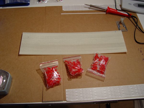
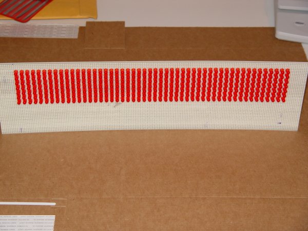
Last week some of you may have saw my post on the LED display. Here is a couple of pics showing my progress and I really could use some help on it. I'm sure there is a formula for calculating resistor value. I have about 500 100 ohm resisitors and thought I could use them for this project? Maybe there is a better solution as to what the proper one to use is.
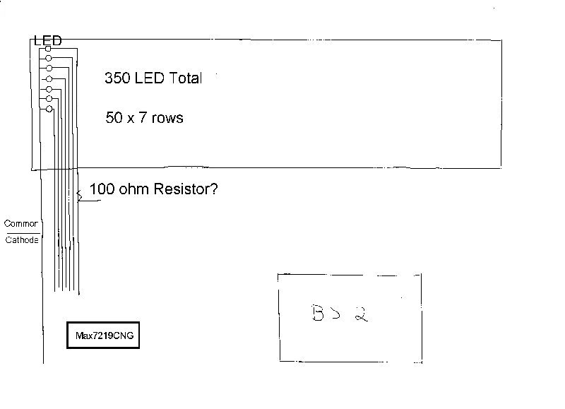
I guess I am at a loss as to how I need to connect everything. I have a BS2 on the way. I have purchased Max7219CNG drivers. The LED's will be common cathode·for use with the 7219 chips. Maybe I·should have read a book·or 2 before starting this project.·Any help anyone could give would be great as I am a good listener and can follow directions. I have searched for similar projects and or signs but nothing is available. Maybe just looking in the wrong places. I have also included my beginning schematic if anyone would like to push it forward a bit....
thanks in advance...
Jeff
Post Edited (slotcarz) : 4/17/2005 5:46:49 PM GMT
Last week some of you may have saw my post on the LED display. Here is a couple of pics showing my progress and I really could use some help on it. I'm sure there is a formula for calculating resistor value. I have about 500 100 ohm resisitors and thought I could use them for this project? Maybe there is a better solution as to what the proper one to use is.
I guess I am at a loss as to how I need to connect everything. I have a BS2 on the way. I have purchased Max7219CNG drivers. The LED's will be common cathode·for use with the 7219 chips. Maybe I·should have read a book·or 2 before starting this project.·Any help anyone could give would be great as I am a good listener and can follow directions. I have searched for similar projects and or signs but nothing is available. Maybe just looking in the wrong places. I have also included my beginning schematic if anyone would like to push it forward a bit....
thanks in advance...
Jeff
Post Edited (slotcarz) : 4/17/2005 5:46:49 PM GMT
600 x 450 - 49K
600 x 450 - 53K
600 x 450 - 46K
800 x 579 - 29K
Comments
▔▔▔▔▔▔▔▔▔▔▔▔▔▔▔▔▔▔▔▔▔▔▔▔
▔▔▔▔▔▔▔▔▔▔▔▔▔▔▔▔▔▔▔▔▔▔▔▔
Jon Williams
Applications Engineer, Parallax
Dallas, TX· USA
cya
Jeff
Check out the robometal, it's basically the same thing only on a smaller scale and done with SX/B. But the schematic and code are available on the Parallax website.
www.parallax.com/detail.asp?product_id=28099
Bean.
▔▔▔▔▔▔▔▔▔▔▔▔▔▔▔▔▔▔▔▔▔▔▔▔
"SX-Video Display Module" Available Now.
www.sxvm.com
"A problem well defined, is a problem·half solved."
·
here's the link if anyone knows...
http://www.maxim-ic.com/appnotes.cfm/appnote_number/2782
thanks again for all the help!
Jeff
By the way, really neat picture. What is the time between the first "puddle of LED's" and the mounted version?
cya
Jeff
cya
and TGIF!!!!!
Jeff
thanks..
In the digit line, will all the positives go to the digit·connection of 1,2,3 etc.? (green line)
In the seg line, will the negatives go to the seg connection of 14,15,16 etc.?( purple line)
I am trying to follow the schematic that Bean posted since that is the closest I have found for my project. My sections will be 7x8 since I have not put in the 8th Led in each column. I think the digits will work better being 7 high. I have the first section soldered up and looks like it is coming apart since the lights all light up with the battery power connected and no signal from the BS2..
thanks...
Jeff
*************
completed and fixed
Post Edited (slotcarz) : 4/22/2005 12:17:19 AM GMT
Had to redo my first section of LEDs since I botched it. I just wired up the first 7x8 section. Have been putting the code together and actually got it to work, well sort of.
I guess I need to look into the max7219 further as I cannot shut off all the LED's to scroll my letters. Could someone help on that? They all come on and the stamp resets and I can see something scrolling but with all the lights on just can't make them out.. Hey I even got a thumbs up from the wife with my project..even though she thinks i'm cookoo for coco puffs..
thanks!
Jeff
Please post your code.
Bean.
▔▔▔▔▔▔▔▔▔▔▔▔▔▔▔▔▔▔▔▔▔▔▔▔
"SX-Video Display Module" Available Now.
www.sxvm.com
"A problem well defined, is a problem·half solved."
·
thanks
Post Edited (slotcarz) : 4/22/2005 12:16:13 AM GMT
If there is someone who could write or help with certain aspects of it, that would be great.
What I would like the sign to do is scroll the word and number of this:
"Hit the Jackpot and Win $xxxx"
x being the amount of the progressive on my slot machine. It's all for fun.
Video File· --
I do not have the grasp on how to write the code·to·scroll thru each segment and I think thats where my problem is.
I have been reading thru the manuals, docs, whatever I can find, but never the right answers. I cannot get the LEds to scroll thru all the led's except for their own segments as you can see in the video. The code was readable the first 3 segment but after putting in different things to try it just doesn't want to cooperate.
I guess the project will be put on hold since my wife and I are leaving the country this Monday to go see our future child we are adopting and won't have time for this right now. That is the highest priority.
I wanted to thank all that have helped me to this point and this is a great site with a great bunch of people.
Hopefully I can get back on track with it...
take it·easy all...
Jeff
Post Edited (slotcarz) : 5/20/2005 8:34:34 PM GMT