

Need help selecting sensor
 Patrick D
Posts: 62
Patrick D
Posts: 62
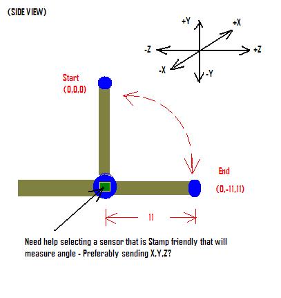
I am trying to make a stamp project that will track movement in 3D.· Let's say that I need to determine where my hand is in relation to my elbow..· For example, assume I am sitting at a table in an "arm wrestling" position.· Every second, I am going to record the position of my hand by measuring the change in the angle between my elbow and hand.·· Now if in this example, the Y-axis is parallel to my spine (i.e. up and down), the X-axis is parallel to the floor and would form a plane that passes through each shoulder (I.e. left and right), and the Z-axis would represent a plane that would represent the area in-front and behind me.·
In this example, lets say I take the starting position of my hand (upright in an "arm wrestling position") and "zero" out the readings.· So, Initially, my hand starts out at an origin (0,0,0) - (for X,Y,Z coordinates).· Next, I move it forward and down so that my forearm is now parallel to the table.· Assuming that my elbow remained on the table and didn't move, and that my forearm is 11 inches, The position of my hand now be something like (0,-11,11).·
Using fairly simple math I could calculate the exact coordinates if·I know two things:
1) the distance from my elbow to my hand
2) the change in the angle at my elbow
With all that said, can anyone suggest a sensor that is Stamp compatible that could be used in a situation like the one above?·
PS - sorry for the long description and lead-up to the question, but I just wanted to be sure that anyone who answered would know what I am trying to do.·
I Have attached an Example image to help describe this...
407 x 431 - 18K
Comments
Can you use potmeters on the elbow to measure the angles? You can read a potmeter easily with a Stamp using RC-time and if you use a clever construction they may give you the XYZ.
I have done a similar thing in 2D with small camera. But I needed a Pentium for the calculations
Regards,
Klaus
Klaus
I thought about the flexiforce sensor but it's a little pricey - especially for prototyping. I haven't ruled anything out... Have you used them?
A joystick pot?
▔▔▔▔▔▔▔▔▔▔▔▔▔▔▔▔▔▔▔▔▔▔▔▔
Beau Schwabe - Mask Designer III
National Semiconductor Corporation
Latest Company News
(Communication Interface Division)
500 Pinnacle Court, Suite 525
Mail Stop GA1
Norcross,GA 30071
Beau - thanks - didn't think about that...· Do you know where I could get my hands on some data sheets?· Ever hear of anyone taking the rotational data from a joystick pot and reading it with a Stamp?
I assume you mean to create a vector between the two pots. Depending on the data that you
really want to react upon, it might be better to keep it separate rather than create a composite value.
Depends on the application and/or method of data handling if this would actually be necessary.
▔▔▔▔▔▔▔▔▔▔▔▔▔▔▔▔▔▔▔▔▔▔▔▔
Beau Schwabe - Mask Designer III
National Semiconductor Corporation
Latest Company News
(Communication Interface Division)
500 Pinnacle Court, Suite 525
Mail Stop GA1
Norcross,GA 30071
to do gait analysis. We later moved to a 3D system that used 4 cameras. To keep cost down instead of using IR cameras, the markers
that we placed on the patient were actually IR beacons that the camera was able to pick up quite nicely. (Aim the TV remote at a video
camera to see what I mean) A simple program to "look" for a specific color generated by the IR Leds provided X and Y coordinates for
each of the sensors from each camera. From here a 3D image could be constructed / represented to collect further information.
▔▔▔▔▔▔▔▔▔▔▔▔▔▔▔▔▔▔▔▔▔▔▔▔
Beau Schwabe - Mask Designer III
National Semiconductor Corporation
Latest Company News
(Communication Interface Division)
500 Pinnacle Court, Suite 525
Mail Stop GA1
Norcross,GA 30071
But I was watchin American Chopper (Mikey rocks!)...well, they had a guy come out with something along the lines of what you're after....
They had to measure the dimensions and such of a frame piece.
This contraption was this odd looking arm with a pen on the end (with aroller).
It didn't mimic the human arm directly..but you could certainly get almost the same dexterity. Anyhow....this had about 5 or 6 joints....single axis joints that were cambered on different angles to give the diflections you were after.
I think the roller pen worked like a mouse basically (encoders..optical or otherwise)...and each joint had some sort of encoder...pot or otherwise that the computer would ingest and calculate (based on each sensors position) where the arm was in space....
Seems simple enough...if you can keep the joints tight enough for resolutions sake....just the math that might get interesting!
▔▔▔▔▔▔▔▔▔▔▔▔▔▔▔▔▔▔▔▔▔▔▔▔
·
Steve
http://ca.geocities.com/steve.brady@rogers.com/index.html
"Inside each and every one of us is our one, true authentic swing. Something we was born with. Something that's ours and ours alone. Something that can't be learned... something that's got to be remembered."
If anyone has any more suggestions, ideas, ec - please let me know
From what I have learned, the high end commercial products use optical based systems like the one you described - therefore I am assuming that it is the preferred technique.· My problem lies in the fact that although I have some programming, engineering and electronics skills, I have no idea in the least how to write a program to do something like that.· Although I do have undergraduate degrees in both Biomedical Engineering and Information Systems, I was never exposed to this type of signal acquisition and analysis, either in college or on the job.· This is why I opted for the “easy” way out.· However, I am not at all opposed to doing anything the “right” way over the “easy” way – I just don’t know where to start.
like to be tethered. With gait analysis, tethering affects the results by restricting or at least giving the
illusion of being restricted to the subject. If you can get your head around 2D graphics, 3D
transformation is not to difficult. There are plenty of programming books out there that deal with
graphic manipulation. Although we had software to do the 3D stuff for us, it was open source with the
equipment we were using. Much of the specialized graphics programming that I did was for 2D points
and normalizing the data in a way that if someone was walking toward or away from you the graphic
points appeared as if they were walking in place (fore shortening normalization). This particular test was
measuring balance symmetry in a before / after situation with a particular device the patient would wear.
▔▔▔▔▔▔▔▔▔▔▔▔▔▔▔▔▔▔▔▔▔▔▔▔
Beau Schwabe - Mask Designer III
National Semiconductor Corporation
Latest Company News
(Communication Interface Division)
500 Pinnacle Court, Suite 525
Mail Stop GA1
Norcross,GA 30071
kelvin