

Pulse waves courtesy of the basic stamp
 boblou
Posts: 10
boblou
Posts: 10
· After teaching the students in my 10th grade electronics class; pulse waves and how to calculate average DC voltge I realized that our suite case lab trainers did not have the ability on the square wave setting to change the pulse width or duty cycle. After much thought I came up with a lab using the homework board as a pulse wave generator in which I could vary the pulse width and base time of the pulse wave. Check it out and see what you think.
·
Pulse waves courtesy of the Basic Stamp
Page #1
····································· Name:
Summary:
········· The Boe-bot is not just an expensive toy that can be programmed to maneuver around in a pattern that continually repeats itself and plays Beethoven.
The top circuit board is an extremely powerful microcontroller using the Basic Stamp IC as an EPROM (erasable programmable read only memory).· The Basic Stamp stores the instructions or programming sequence and turns a program into I/O commands.·
··········· We can program the Homework PCB or the full (Board of Ed) to control almost any electronic function.· In this mini lab we will program the controller in Pbasic to produce pulse waves on a designated I/O pin.· Through programming we have the capability of varying the time or repetition rate (frequency).· The lab trainer can produce only a square wave (pulse wave with a 50% duty cycle).· The controller has the ability of producing variable pulse widths (tw), which can give us, pulse waves of changeable duty cycles.· We can accomplish this all with slight variations in our Pbasic program.·
·
Procedure:
········· 1.· We will use some of the following commands:
a.····· Declaration (tells Pbasic which basic stamp is in use)
b.····· Naming a variable (example cat var word)
c.······ Loops
d.····· Pause
e.····· For/next
f.······· Goto
g.····· Output commands
·
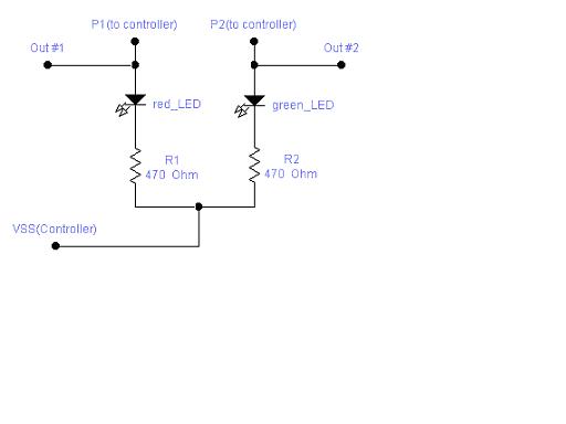
2.· Build the simple 2 Led circuit on the white board of the controller as shown in the schematic below:
········· ·······················
·
···················· Note: The schematic is on the image attachment
···········
3.····· Enter the program into the computer as shown below and down load it in to the controller.
·
{ BS2 }····················································· ‘ Declares the type of basic stamp
·Output 1
·Loop:
·Out1=1
·Pause 100
·Out1=0
·Pause 100
·Goto loop
·
·
Page #2
4.····· When you run the program what happens? Explain your answer.
·
5.····· Do both Leds blink? Explain your answer.
·
6.····· Enter into the program in step #3 a remark explaining what each program line does.· I have shown an example on the first line {BS2}.
·
7.····· Disconnect the controller from the I/O cable and bring the board over to the scope to be tested.
·
8.····· Connect the Oscilloscope to the controller board with the red lead to Out #1, and the black lead to VSS.··
·
9.····· Explain the results.
·
10.· ·Connect the DMM to the red and black scope leads and set it to DC on the 20V scale.· Record the voltage·· Out #1 =·
·
11.· ·Now connect the red lead to VDD of the controller and record the voltage.··· VDD =
·
12.· ·How do the voltages in step #10 and #11 compare?··
·
13.· ·How can you modify the program to increase the repetition rate?
·
·
14.· ··Try modifying the program to give you a repetition rate of 10ms and a pulse width (tw) of 3ms.· After you have changed the program test it on the scope and check out the waveform.· You may have to use trial and error to achieve the desired results.·
·
15.· Call your instructor over to check your results.· I will be looking at the pulse wave and the average voltage on the DMM.
·
16.· ·Calculate the average voltage.·· VAvg = ________
·
17.· Modify the program in step #14 so the pulse width is now 7ms with the repetition rate still at 10ms.· Call over Mr. F. to check your results.
·
18.· ·Calculate the average voltage.·· VAvg = _______
·
19.· ·Your next challenge will be to have both Leds blinking.· You will have the red Led on and the Green Led off, and when the Red is off the Green will be on.· Note: Refer to the original program in step #3.
·
·
·
Page #3
20.·········· ·The challenge:· You will now add the photo-resistor and a resistor to the original circuit to control the blinking of the Leds.· Your program will perform the following function:· The red Led will only blink when the controller is in the dark or the sensor is covered.· The green Led will blink only if the photo-resistor is exposed to light.· You will need to write a new program so first save the original program.
·
·
·
Pulse waves courtesy of the Basic Stamp
Page #1
····································· Name:
Summary:
········· The Boe-bot is not just an expensive toy that can be programmed to maneuver around in a pattern that continually repeats itself and plays Beethoven.
The top circuit board is an extremely powerful microcontroller using the Basic Stamp IC as an EPROM (erasable programmable read only memory).· The Basic Stamp stores the instructions or programming sequence and turns a program into I/O commands.·
··········· We can program the Homework PCB or the full (Board of Ed) to control almost any electronic function.· In this mini lab we will program the controller in Pbasic to produce pulse waves on a designated I/O pin.· Through programming we have the capability of varying the time or repetition rate (frequency).· The lab trainer can produce only a square wave (pulse wave with a 50% duty cycle).· The controller has the ability of producing variable pulse widths (tw), which can give us, pulse waves of changeable duty cycles.· We can accomplish this all with slight variations in our Pbasic program.·
·
Procedure:
········· 1.· We will use some of the following commands:
a.····· Declaration (tells Pbasic which basic stamp is in use)
b.····· Naming a variable (example cat var word)
c.······ Loops
d.····· Pause
e.····· For/next
f.······· Goto
g.····· Output commands
·
2.· Build the simple 2 Led circuit on the white board of the controller as shown in the schematic below:
········· ·······················
·
···················· Note: The schematic is on the image attachment
···········
3.····· Enter the program into the computer as shown below and down load it in to the controller.
·
{ BS2 }····················································· ‘ Declares the type of basic stamp
·Output 1
·Loop:
·Out1=1
·Pause 100
·Out1=0
·Pause 100
·Goto loop
·
·
Page #2
4.····· When you run the program what happens? Explain your answer.
·
5.····· Do both Leds blink? Explain your answer.
·
6.····· Enter into the program in step #3 a remark explaining what each program line does.· I have shown an example on the first line {BS2}.
·
7.····· Disconnect the controller from the I/O cable and bring the board over to the scope to be tested.
·
8.····· Connect the Oscilloscope to the controller board with the red lead to Out #1, and the black lead to VSS.··
·
9.····· Explain the results.
·
10.· ·Connect the DMM to the red and black scope leads and set it to DC on the 20V scale.· Record the voltage·· Out #1 =·
·
11.· ·Now connect the red lead to VDD of the controller and record the voltage.··· VDD =
·
12.· ·How do the voltages in step #10 and #11 compare?··
·
13.· ·How can you modify the program to increase the repetition rate?
·
·
14.· ··Try modifying the program to give you a repetition rate of 10ms and a pulse width (tw) of 3ms.· After you have changed the program test it on the scope and check out the waveform.· You may have to use trial and error to achieve the desired results.·
·
15.· Call your instructor over to check your results.· I will be looking at the pulse wave and the average voltage on the DMM.
·
16.· ·Calculate the average voltage.·· VAvg = ________
·
17.· Modify the program in step #14 so the pulse width is now 7ms with the repetition rate still at 10ms.· Call over Mr. F. to check your results.
·
18.· ·Calculate the average voltage.·· VAvg = _______
·
19.· ·Your next challenge will be to have both Leds blinking.· You will have the red Led on and the Green Led off, and when the Red is off the Green will be on.· Note: Refer to the original program in step #3.
·
·
·
Page #3
20.·········· ·The challenge:· You will now add the photo-resistor and a resistor to the original circuit to control the blinking of the Leds.· Your program will perform the following function:· The red Led will only blink when the controller is in the dark or the sensor is covered.· The green Led will blink only if the photo-resistor is exposed to light.· You will need to write a new program so first save the original program.
·
·
512 x 384 - 10K