

RC time constant program
 boblou
Posts: 10
boblou
Posts: 10
·
·
I teach 10th grade Electronics at a vocational H.S in CT.
I used this circuit after I went thru RC time constants with my high school Electronic students. The programming is simple and it appears to work for various values of capacitors. Try keeping the time constant greater then one second.
·
Note: The schematic is on the image slide
·
·
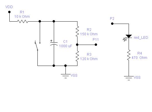
2. R2 and R3 make up a voltage divider, that will allow P11 to reach 1.4 volts when the capacitor gets to 3.15V·· Lets do the math using the voltage divider formula.
·
Voltage P11=············ R3
··························· ·_________· *· 3.15······ 120K/270K·· * 3.15 = 1.4V
····························· R2 + R3
·
3. When P11 reaches 1.4V it will satisfy the program P11 =1. The Debug program will show the amount of time for the capacitor to equal one time constant or 63% of VDD. Your time will be in milli-seconds. Remember that electrolytic capacitors are generally > in value then the marked value so your time will be slightly > the calculated time.
·
4. The switch is used to completely discharge the capacitor. To start the timing program hold down both the discharge switch and the reset switch on the control PCB.· Pushing down the reset switch allows the program to reset and start at the first program line. Now when your are ready release both switches at the same time.
·
5. I used a 10k resistor and a 1000ufd capacitor. Try experimenting with different values of R and C. Make sure the values of R2 and R3 are > 10 times the value of R1 your timing resistor.
·
[list=6][*]Please let me know your results, ideas, ·or comments.[/list]
·
·
·
·
·
' {$STAMP BS2}
' {$PBASIC 2.5}
·
OUTPUT 2·················· ··························' Goes high when capacitor is at 63% VS
OUTPUT 11·········· ································' Analog voltage increasing to 1.4V
·
time VAR Word
s VAR Word
charge VAR Word
·
·
time=0························ ····························' Starting point of time counter
OUT2=0
IN11=0
DEBUG· CLS
DEBUG "capacitor is discharged",CR,CR
DEBUG "One time constant = 63% of VS",CR,CR
·
·
·
repeat:
IF IN11=1 THEN charged
time=time+1
PAUSE 10
GOTO repeat
charged:
charge=time *12
OUT2=1····················· ······························'Red LED lights when cap is @ 63% VS
·
·
DEBUG "Vcap= 3.15V (63% of 5volts)· ·time TO charge is· ",DEC charge, " ms"
·
·
·
·
I teach 10th grade Electronics at a vocational H.S in CT.
I used this circuit after I went thru RC time constants with my high school Electronic students. The programming is simple and it appears to work for various values of capacitors. Try keeping the time constant greater then one second.
·
Note: The schematic is on the image slide
·
·
- R1 and C1 make up the RC time constant.· T = R1*C1 after one time constant C1 will equal 63% of VDD or 3.15V since VDD=5V.· Since the voltage divider values(R2 and R3) are much greater then 10 times R1 in value the loading effect across the capacitor can be neglected.
2. R2 and R3 make up a voltage divider, that will allow P11 to reach 1.4 volts when the capacitor gets to 3.15V·· Lets do the math using the voltage divider formula.
·
Voltage P11=············ R3
··························· ·_________· *· 3.15······ 120K/270K·· * 3.15 = 1.4V
····························· R2 + R3
·
3. When P11 reaches 1.4V it will satisfy the program P11 =1. The Debug program will show the amount of time for the capacitor to equal one time constant or 63% of VDD. Your time will be in milli-seconds. Remember that electrolytic capacitors are generally > in value then the marked value so your time will be slightly > the calculated time.
·
4. The switch is used to completely discharge the capacitor. To start the timing program hold down both the discharge switch and the reset switch on the control PCB.· Pushing down the reset switch allows the program to reset and start at the first program line. Now when your are ready release both switches at the same time.
·
5. I used a 10k resistor and a 1000ufd capacitor. Try experimenting with different values of R and C. Make sure the values of R2 and R3 are > 10 times the value of R1 your timing resistor.
·
[list=6][*]Please let me know your results, ideas, ·or comments.[/list]
·
·
·
·
·
' {$STAMP BS2}
' {$PBASIC 2.5}
·
OUTPUT 2·················· ··························' Goes high when capacitor is at 63% VS
OUTPUT 11·········· ································' Analog voltage increasing to 1.4V
·
time VAR Word
s VAR Word
charge VAR Word
·
·
time=0························ ····························' Starting point of time counter
OUT2=0
IN11=0
DEBUG· CLS
DEBUG "capacitor is discharged",CR,CR
DEBUG "One time constant = 63% of VS",CR,CR
·
·
·
repeat:
IF IN11=1 THEN charged
time=time+1
PAUSE 10
GOTO repeat
charged:
charge=time *12
OUT2=1····················· ······························'Red LED lights when cap is @ 63% VS
·
·
DEBUG "Vcap= 3.15V (63% of 5volts)· ·time TO charge is· ",DEC charge, " ms"
·
·
·
520 x 384 - 13K