

Newbie to Stamp and electronics (little step U)
 sector
Posts: 2
sector
Posts: 2
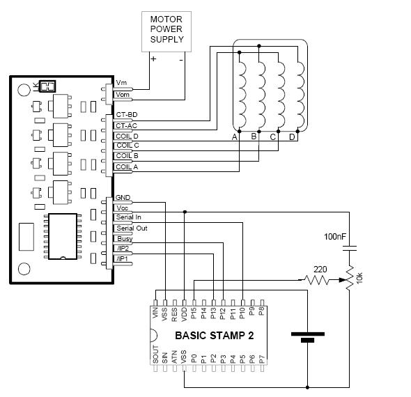
I really need help getting started, som parts i understand but only the parts in the books, how the heck do i for example connect a little step-u unit to the basic stamp. I got the scheme but i dont know what the symbols means. I dont want to destory my components by connecting them wrong. What i am trying to do is to connect a stepper mottor, that part i understand but not the connection betwen Stamp and Little step-u,, could anyone please tell me what the symblos means, for example the to dark thick lines, one halv as long as the one above, it looks like gnd, but probably it isn´t. Plz look at the attachment, i would be very happy if someone could explain to me what to do. Thanks!
590 x 570 - 41K
Comments
·· The dark thick line you described is actually the battery/power source.· The longer end is the positive terminal.· The shorter end is the negative terminal, and is connected to the Vss (Ground) pin on the stamp.· Likewise, the GND pin on the Little Step-U is connected to the other Vss pin, so there is a common ground.
·· What else don't you understand?· The pins on the Little Step-U should be in the docs for it.
▔▔▔▔▔▔▔▔▔▔▔▔▔▔▔▔▔▔▔▔▔▔▔▔
Chris Savage
Parallax Tech Support
csavage@parallax.com
Chris has explained the battery symbol and the others (resistor, pot and capacitor) are covered in the Basic Stamp manual. They are used in this application to demonstrate a method for varying the speed. They aren't required in the simplest configuration to get the motor moving. Also connected in the circuit you have posted are the BUSY and /IP2 pins. They are used in the application code, but aren't required for a minimal setup.
I have attached a 'minimum' circuit diagram. I would suggest wiring up that circuit, get the motor moving and then add on a piece at a time.
A minimum program to match might be -
pause 200 ' Let everything get stable
serout 10, 396,[noparse][[/noparse]"{E100}"] ' Use default settings and move 100 steps
end
Steve.
Michael