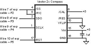
Vector 2x Heading seems to be off - any ideas?
Just hooked up the Vector2x to my BS2. Code is below (circuit and code is same as http://www.robotics.com/arobot/vector.html)
Seems as though my headings are off by about 90 degrees.
The only thing I can think off is that I have YFlip grounded along with RES (as per the schemtatic at the above link (and attached).
Any ideas????
' {$STAMP BS2}
' {$PBASIC 2.5}
'
'compass signals.
slct CON 2 'select signal.
sdo CON 3 'serial data out.
sclk CON 4 'clock signal.
rst CON 5 'reset signal.
'Other.
heading VAR Word 'heading variable.
setup:
OUTPUT slct 'set pin direction.
OUTPUT sclk
OUTPUT rst
INPUT sdo
GOSUB compinit 'initialize the compass.
main:
GOSUB getcomp 'get the compass heading.
DEBUG DEC ? heading 'Display heading.
DEBUG CR
PAUSE 1000 'wait a sec.
GOTO main 'loop for ever.
'
'this routine initializes the Vector 2x compass.
'
compinit:
HIGH sclk
HIGH slct 'make sure this is high.
LOW rst 'lower reset pin.
PAUSE 15 'wait 15 ms.
HIGH rst 'raise reset pin.
PAUSE 200 'wait a bit.
RETURN 'done.
'
'This routine gets the heading from the Vector 2x
'compass and places it in the variable heading.
'
getcomp:
LOW slct 'start the Vector 2x.
PAUSE 200 'wait for heading.
heading = 0 'clear variable.
SHIFTIN sdo,sclk,MSBPRE,[noparse][[/noparse]heading\16]
'get the data from Vector 2x.
HIGH sclk 'reset pins.
HIGH slct
RETURN 'done.


Comments
▔▔▔▔▔▔▔▔▔▔▔▔▔▔▔▔▔▔▔▔▔▔▔▔
Jon Williams
Applications Engineer, Parallax
Dallas, TX· USA
The compasses are able to detect very weak magnetic fields and could be thrown off by a piece of steel for example. Has anyone ever told you you they thought you had a "magnetic personnality"
The compass is at least 2 ft away from any circuits, motors, or metallic objects.
I find it interesting that the readings are 90degrees off, vs varying amounts, which is what I would expect if there was a magnetic field nearby.
The manual states to take XFLIP pin high, and YFLIP pin low.
I do not have XFLIP connected to any pins , and YFLIP is grounded to VSS. Is this the same as having XFLIP high and YFLIP low?
and ya tying to ground is tying low
you could also drive it high with a stamp pin and resistor in series. Resistor is used to limit current.
Post Edited (Jonb) : 3/9/2005 7:27:03 PM GMT
HIGH 10
I think this should work?
GL!
Post Edited (Jonb) : 3/9/2005 7:34:36 PM GMT
Also, going to mount this vector 2x in my car - any optimum localtion? thinking in the center console, away from the radio, speakers, etc.....
Any magnetic distortions would cause heading errors that would vary as the unit was rotated in a circle, not a 90 degree offset.
Julian Benton
Applications Engineer
PNI Corporation
jbenton@pnicorp.com
So it seems that I do not need to tie XFLIP to anything.....