

Project planning - Need some input from you guys!
 WhipeOut
Posts: 13
WhipeOut
Posts: 13
Hi!
I'm a newbie to the BS world so I guess you'll see me here with a lot of questions from now on. [noparse];)[/noparse]
I need some input and thought about a project I've been thinking of. Hear me out.
Components
BASIC Stamp 2p 24-Pin Module
4x4 Keyboard
4x20 LCD display
# Relays
Project:
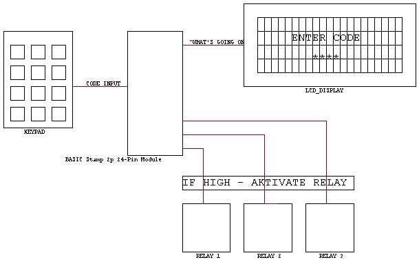
In short terms: I'd like to use a "PIN-code" (Personal ID Numer) input on the keyboard to activate a sertain relay by using a BS. The LCD displays what to do and what's going on.
I've attached a drawing that show's my project the easiest way.
(Parallax Description.jpg)
Need more description?
Description.
When I enter a PIN-code of 4 digits on the keypad, the BS detects what numbers I've entered and wich order they are entered. The BS is then checks if this exact order and numbers are a PIN-code that aktivates something. If it doesn't recognize the code, the LCD displays "Incorrect PIN" or something like that. If the code is recognized, an I/O port shall go HIGH and aktivate the relay that is connected to the exact I/O pin. (OPAMP if necessary) Now the LCD displays "RELAY 1 AKTIVATED" for 10sec, and then returns to the "Enter Code" mode. Now the BS is ready to get another code that aktivates another relay. If a relay is aktivated, it can be deaktivated by entering the same code one more time, and LCD displays "RELAY 1 DEAKTIVAED".
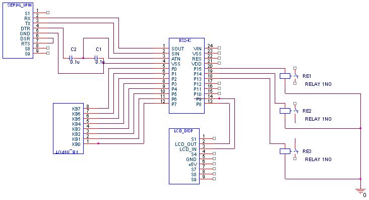
If I'd like to change these codes without removing the BS from the circuit, it can be solved by attaching a 9pin Serial connector to the Print card.
I'v attached a circuit drawing made in OrCAD. It's a little more details on this one.
(Parallax Pin.jpg)
Well, what do all you folks out there think?? It's for a school project, so it better work... [noparse];)[/noparse]
Was this understandable?
Thoughts??
Thanks.
WhipeOut
I'm a newbie to the BS world so I guess you'll see me here with a lot of questions from now on. [noparse];)[/noparse]
I need some input and thought about a project I've been thinking of. Hear me out.
Components
BASIC Stamp 2p 24-Pin Module
4x4 Keyboard
4x20 LCD display
# Relays
Project:
In short terms: I'd like to use a "PIN-code" (Personal ID Numer) input on the keyboard to activate a sertain relay by using a BS. The LCD displays what to do and what's going on.
I've attached a drawing that show's my project the easiest way.
(Parallax Description.jpg)
Need more description?
Description.
When I enter a PIN-code of 4 digits on the keypad, the BS detects what numbers I've entered and wich order they are entered. The BS is then checks if this exact order and numbers are a PIN-code that aktivates something. If it doesn't recognize the code, the LCD displays "Incorrect PIN" or something like that. If the code is recognized, an I/O port shall go HIGH and aktivate the relay that is connected to the exact I/O pin. (OPAMP if necessary) Now the LCD displays "RELAY 1 AKTIVATED" for 10sec, and then returns to the "Enter Code" mode. Now the BS is ready to get another code that aktivates another relay. If a relay is aktivated, it can be deaktivated by entering the same code one more time, and LCD displays "RELAY 1 DEAKTIVAED".
If I'd like to change these codes without removing the BS from the circuit, it can be solved by attaching a 9pin Serial connector to the Print card.
I'v attached a circuit drawing made in OrCAD. It's a little more details on this one.
(Parallax Pin.jpg)
Well, what do all you folks out there think?? It's for a school project, so it better work... [noparse];)[/noparse]
Was this understandable?
Thoughts??
Thanks.
WhipeOut
609 x 380 - 27K
732 x 396 - 37K
Comments
And you probably will want some decoupliing caps (.1uf, .01uf) between the power and ground pins on the bs2 (put them as close to the power in and ground on the bs2 as you can).
Don't know if that helps out any.. but it is very important... Also, when the bs2 powers up.. you might see the relays 'activate' whatever is behind them.
Also, at an added expense, but reduced wiring and programming complexity, you could use www.parallax.com/detail.asp?product_id=30057 which is a 2x20 LCD which has a built-in keypad interface.
Jim
Trend:
Don't think I reallt understood the "decoupliing caps" part. Do you have an example that might help. Picture of such a setup or anything?
About the relays. The point is that I have a circuit, let say a battery and a light bulb. This circuit is broken by the relay. As the relay get something from the BS, it'll complete the circuit, and "let there be light".
Jim:
Was thinking of using this display http://www.parallax.com/detail.asp?product_id=30058
It has a built-in keybpad interface aswell.
Do you have an example where the keypad is connected to the LCD and further into the BS?
Thanks,
WhipeOut
Yup. That would work as well. The keypad, if your using the Matrix keypad from Parallax, is connected to the LCD controller by a cable also sold by Parallax. The LCD controller is then connected to the Stamp via serial or I2C. Since you're using the BSP2p (serious overkill for this project) you have the I2CIN and I2COUT commands, so I'd use the I2C connection. The keypad sends row/column connections to the LCD controller which in turn translates them to ASCII and sends them on to the Stamp via the data connection. As far as communicating, if you're using I2C, you send display commands to the LCD display via I2COUT and receive keypad input via I2CIN.
Jim
That sounds like a good solution. And the LCD controller send the input from the keypad as the have been enterd. Sweet.
I know that the BSP2p is a serious overkill for this, but this is only a excuse to make the school buy me a Stamp and the other components. [noparse];)[/noparse] Sweet...
Is there anyone out there that have some source code for something like this?
Thanks,
WhipeOut