Shop OBEX P1 Docs P2 Docs Learn Events
Logic Probe — Parallax Forums

Logic Probe

MacGeek117MacGeek117 Posts: 747
edited 2005-02-16 15:45 in BASIC Stamp
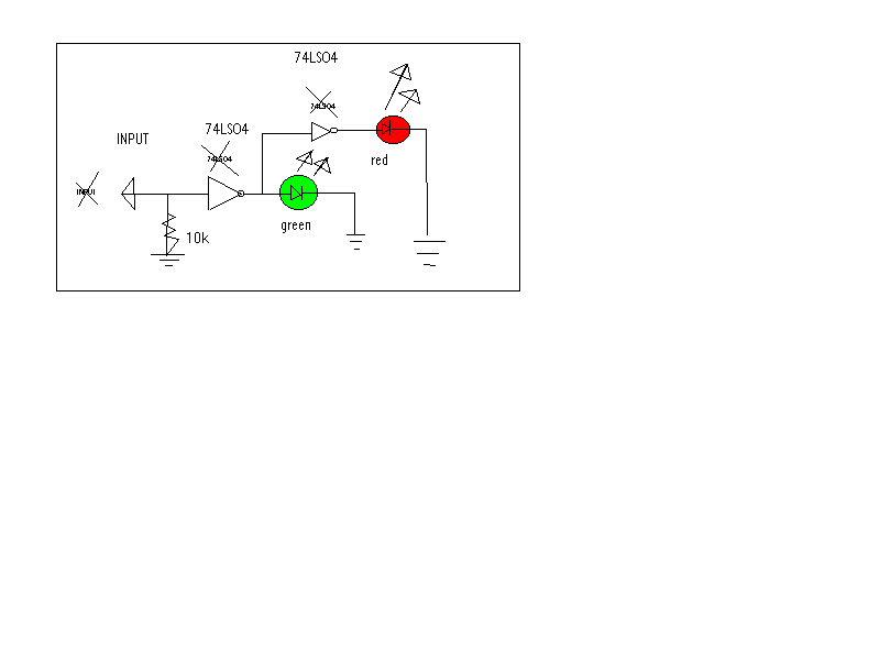
If anyone wants to know, here is a circuit for a logic probe:
devil.gif

▔▔▔▔▔▔▔▔▔▔▔▔▔▔▔▔▔▔▔▔▔▔▔▔
I think I know what I'm doing...

Comments

  • allanlane5allanlane5 Posts: 3,815
    edited 2005-02-13 21:06
    Cool, but most logic probes have 'pulse-stretchers' to make short pulses visible.
  • Pinoy NYCPinoy NYC Posts: 30
    edited 2005-02-14 21:52
    you can also remove the inverter for red led
    and wire it to the input side of the green led's inverter.
  • NeilBNeilB Posts: 9
    edited 2005-02-15 19:07
    >>you can also remove the inverter for red led
    >>and wire it to the input side of the green led's inverter.

    Considering that the builder of the logic probe has no knowledge of the current sourcing capability of the input, the original configuration would be preferred. Putting the red LED input before the the inverter shows a diode load to the input. The OPs configuration shows a high impedence load.
  • Paul BakerPaul Baker Posts: 6,351
    edited 2005-02-15 19:16
    actually the 10k resistor drop makes the input to the circuit not a high impedance input, 10k is usually consider neither high nor low impedance, >1MOhm is typically considered high impedance. But for a steady state input (non changing), which is what the circuit was designed to measure, the 10k resistor is sufficient to not effect the logic level of the circuit. I was going to mention this aspect (not a high impedance input) when he first posted the circuit, but realized that for the circuit's intended purpose this wasn't an issue, so I didn't.
  • MacGeek117MacGeek117 Posts: 747
    edited 2005-02-16 15:45
    Also, guys, if I get a pulsating signal, I can just load this program on my BS2 and go. smurf.gif

    ▔▔▔▔▔▔▔▔▔▔▔▔▔▔▔▔▔▔▔▔▔▔▔▔
    I think I know what I'm doing...
    ...Maybe...

    Post Edited (bugg) : 2/16/2005 3:55:13 PM GMT
Sign In or Register to comment.