Transistor Switch
Hi everyone,
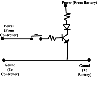
Not exactly Basic Stamp related, but this has been a problem that I have been unable to find a solution to. I'm creating a device to work with a Playstation 2 (A DDR pad for those familiar with it). The idea is to press down on a panel with your foot and create a circuit by connecting the power and ground from one button on the controller. Well, that works great. Now, I would like to have that panel light up when you press down. The first thought was to have a transistor turn on two LEDs. However, I either get only lights or only the button working depending on the arrangement. I attached a drawing of the current circuit.
What I believe is happening is if I don't put the battery in, then the controller work fine since it's going from the base straight to ground and getting the full 3.5V that the controller puts out. However, if I put the batter in, then the voltage out of the transistor is 0, which saturates the transistor but does not work the controller. What do I need to do to make this work? Should I try something else, or just need a different arrangement? I would appreciate any help. Hope the drawing is clear. It's just a basic transistor switch. Thanks!
David
Post Edited (Gecko Studio) : 2/11/2005 11:05:09 PM GMT


Comments
If you draw the circuit with the post, it will get crushed.
bugg
▔▔▔▔▔▔▔▔▔▔▔▔▔▔▔▔▔▔▔▔▔▔▔▔
I think I know what I'm doing...
bugg
▔▔▔▔▔▔▔▔▔▔▔▔▔▔▔▔▔▔▔▔▔▔▔▔
I think I know what I'm doing...
David
connect a 10k Ohm resistor between the controller and ground.
bugg
▔▔▔▔▔▔▔▔▔▔▔▔▔▔▔▔▔▔▔▔▔▔▔▔
I think I know what I'm doing...
Thanks for the suggestion. I tried that, the controller works, but the LEDs only flicker for a brief moment and don't come on. I tried higher values, but at about 100k only the lights work. It seems to be either-or at this point. I'm positive this can be done, but just not sure how. Somehow, I need to be able to send the original control voltage back to the controller, but run the lights off the battery and control both with only one switch. Any other suggestions? thanks again for the speedy help.
David
bugg
▔▔▔▔▔▔▔▔▔▔▔▔▔▔▔▔▔▔▔▔▔▔▔▔
I think I know what I'm doing...
bugg
▔▔▔▔▔▔▔▔▔▔▔▔▔▔▔▔▔▔▔▔▔▔▔▔
I think I know what I'm doing...
bugg
▔▔▔▔▔▔▔▔▔▔▔▔▔▔▔▔▔▔▔▔▔▔▔▔
I think I know what I'm doing...
bugg
▔▔▔▔▔▔▔▔▔▔▔▔▔▔▔▔▔▔▔▔▔▔▔▔
I think I know what I'm doing...
1. A 4.7k resistor makes the controller work, but not the LEDs.
2. The switch on the pad works fine. I'm just trying to add light to it. this was one suggestion given (to use a transistor) but no one seemed to know how to make it work. The lights are just a visual, and if I can't find a way to add them, then all's not lost, just not as flashy
If anyone comes up with other ideas, let me know. Bugg, again thanks for the help. I owe you one.
David
FYI, the configuration is called an emitter follower.
Not drawn, but you seem to be aware from your original drawing, the ground for the 9v battery and the ground from the power source need to be tied together.
Ken
David
The circuit I posted assumed that the voltage to the switch would be 9 volts.
If the voltage to the switch is less than 8.2 volts, the circuit "should not" work. Even at 8.2 volts the current through the LEDs will be minimal.
The reason is that when using an emitter follower, the emitter voltage will be one diode drop (~0.6) volts less than the base voltage.
Each LED using 3.8 volts X 2 = 7.6 volts, plus 0.6 = 8.2 volts, but very little current through the LEDs because of the 330 ohm resistor.
I wondered if the arrangement would do anything to the transistor. However, being used in a switch format I figured that it would limit any wear on it. A little bit of shortened life span isn't a big deal (it'll be in an easy to replace area). thanks for the info on that Paul. Ken, thanks for the background on the circuit. That arrangement may work well for other projects, so I'll keep it in mind. So glad to have a great group of people to help out this lost soul!
David