

Controling Solenoid
 earthlingzed
Posts: 14
earthlingzed
Posts: 14
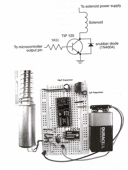
I am trying to control a solenoid from my BS2 using a circuit like the one shown in the attached picture.
I am very new to electronics and having trouble figuring out how to get my 24VDCsolenoid enough power using a TIP120 Darlington Transistor. The current coming in on the base is just under 5V and what is coming out to the solenoid is about 3.5V (roughly). My program is working fine and the solenoid is clicking and giving a very faint tug when it gets power as controled by the BS2, but not near enough. How do I amlify the power enough to operate the solenoid which needs 24V but will work okay at 12V? Is there an equation for calculating the power amplification?
My goal is to control 4 once I have this figured out. Is it better to buy some sort of motor control?
450 x 597 - 34K
Comments
If you run them at half the voltage, you might find that you need twice the current....so you run out of regulator room quickly.
(just a note....current is in Amps....you are measuring 5volts on the base of the darlington.)
The 5V on the base is about right...as the stamp puts out 5V and you have a series resistor so it drops a little.
I was surprised to see the diode across the emitter/collector....if it's purpose is to prevent back-EMF from hitting the stamp, then I'd have thought it'd be across the coil (like in a relay).·
What's the voltage across your coil?
Where are you measuring that 3.5V?· if that's all you have at the solenoid, then there's no way that'll make it go (especially if it's a 24V one).
You'll need·a separate supply....use a 24Vdc wall-wart.
▔▔▔▔▔▔▔▔▔▔▔▔▔▔▔▔▔▔▔▔▔▔▔▔
·
Steve
http://members.rogers.com/steve.brady
"Inside each and every one of us is our one, true authentic swing. Something we was born with. Something that's ours and ours alone. Something that can't be learned... something that's got to be remembered."
The actual voltage is not indicated on your diagram, but thats what it needs to be. The TIP120 is acting as a switch. When the Base is at zero volts, the TIP120 is a low-resistance path to ground for the Solenoid current. When the base is at +5 volts, the TIP120 is a high-resistance path (aka "Off") to current, and the Solenoid should release.
And using the TIP120 is probably the best (most robust, least expensive) approach to doing this.· You're on the right track.
Can you give me some sort of specific diagram or example of how to handle supplying power to 4 solenoids from one source? Do they each need their own power source?
Also, I am a serious newbie. What is a wall-wart?
You can drive 4 solenoids -- I believe from unregulated power, in fact -- from a single 24 volt supply. You might check the current needs of the solenoid -- a TIP120 can handle 5 amps, which is HUGE.· This means the TIP120 will not be stressed by your application.·You probably don't need that much current to activate the solenoid, but you'll have to read up on your specific solenoid for that.
So, if your solenoid takes 500 mA to activate, and you want 4 of them, you'll need a 2 amp, 24 volt supply. If your solenoid takes 100 mA to activate, you'll only need a 400 mA supply.
Dave
·· Just seems like it would make a nice heat source at that current!
▔▔▔▔▔▔▔▔▔▔▔▔▔▔▔▔▔▔▔▔▔▔▔▔
·
Steve
http://members.rogers.com/steve.brady
"Inside each and every one of us is our one, true authentic swing. Something we was born with. Something that's ours and ours alone. Something that can't be learned... something that's got to be remembered."
I am searching for teh current rating for my solenoids which I got at AllElectronics.com but nothing is listed when searched for via google. Will I overload my solenoids with the above power supply which is rated at 1000mA?
But, it says "Intermittant Duty; Max 10%"
On another site ( http://www.magnet-schultz.com/404%20DC%20PULL%20TYPE%20SOLENOID.htm·) they call Intermittant 11Watts.
SO, here comes the math, at 24Volts and 11Watts you would be pulling a max current of P=VI; I=P/V=11/24=458mA (or close enough to say 500mA).
So with 4 solenoids at FULL draw, you'd be at your power supply limit.·
So, I'd say that's probably fine as longas you're not firing all solenoids at once.
▔▔▔▔▔▔▔▔▔▔▔▔▔▔▔▔▔▔▔▔▔▔▔▔
·
Steve
http://members.rogers.com/steve.brady
"Inside each and every one of us is our one, true authentic swing. Something we was born with. Something that's ours and ours alone. Something that can't be learned... something that's got to be remembered."
The diode across the transistor provides back-EMF protection ONLY to the transistor. By not placing a diode across the coil(s), then other components in your
circuit are vulnerable to back-EMF damage. As a rule of thumb, placing diodes across all inductive loads is required. Placing diodes across transistors and other
sensitive components is preferred but not absolutely required.
▔▔▔▔▔▔▔▔▔▔▔▔▔▔▔▔▔▔▔▔▔▔▔▔
Beau Schwabe - Mask Designer III
National Semiconductor Corporation
(Communication Interface Division)
500 Pinnacle Court, Suite 525
Mail Stop GA1
Norcross,GA 30071
That power supply is NOT GOOD for what you want to do AT ALL.
Regarding Current -- see
http://forums.parallax.com/showthread.php?p=524963
and scroll down to my treatise on current, the dependent quantity.
In your case, you're not driving an LED, but the base of the TIP120.· And then, the TIP120 is providing low or high resistance for the coil.· The coil has a certain resistance associated with it -- and that limits your current.
Post Edited (allanlane5) : 2/9/2005 7:12:24 PM GMT
http://www.radioshack.com/product.asp?catalog%5Fname=CTLG&product%5Fid=273-1776
is a 12-volt, 1000 mA (or 1 Amp) AC to DC converter for $18.
Search for "AC-To-DC" to get the full range.· There is a 'Regulated' one:
http://www.radioshack.com/product.asp?catalog%5Fname=CTLG&product%5Fid=273-1680
The difference between 'regulated' and 'unregulated' (besides price) is that the 'regulated' one has some linear regulator built in.· This is a 7805 or equivalent device which keeps the output voltage fixed no matter how the load changes.· 'Unregulated' has more ripple, and the voltage changes based on the current you are pulling.
You can at least test your relays with the $18 model (or the 13.5 volt model, for that matter).· You need to find how much current they pull when activated, and when 'holding', to know if you need more current than the $18 until can put out.
·
I got the recommended 12 VDC 1000 mA power supply for my solenoid circuit and I have it set up.
I am not getting the solenoid to contract at all.
Here is what I know thus far:
Using a simple program to turn it on , pause, then turn it off
' {$STAMP BS2}
' {$PBASIC 2.5}
main:
HIGH 7
PAUSE 200
LOW 7
PAUSE 2000

GOTO main
The BS2 is properly putting out 3V going into a 1k Ohn resistor, then into my TIP120 Base.
My diode goes across the collector and the emitter.
It looks like the emitter never lets out any voltage. It stays at 0.
The collector emits between 1.2V and 2.2V as the progam toggles.
I am getting 12V in from the solenoid power supply.
The solenoid stays at 0V, never getting any power.
I have the emitter going to the ground for both the solenoid power supply and the BS2 as it is my understanding that the circuit will not work without doing this.
I am so damned lost. I think I am following the correct circuit to a T, but it is not working!
Post Edited (earthlingzed) : 2/15/2005 9:07:40 PM GMT
I am not even certian what to test next to solve the problem.
BTW emitter should be 0V since its tied to ground, but the collector should vary between ~12V and
Post Edited (Paul Baker) : 2/15/2005 10:03:19 PM GMT
Dave
Hope Im clear in my explaination.
Shawn Lowe
▔▔▔▔▔▔▔▔▔▔▔▔▔▔▔▔▔▔▔▔▔▔▔▔
Shawn Lowe
Remember - No matter where you go
There you are.