

New SX Proto Board Preview
 John B
Posts: 82
John B
Posts: 82
Hi there,
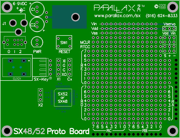
Attached you will find an image of the new SX48/52 Proto Board.· Please review and comment.· Your suggestions will be incorporated into the new design (if approved).
Here are a list of features:
Supports either the SX48 or the SX52
· All surface mount components (yes,·the SX too)·included and soldered to the pcb.
· All I/O pins accessible
· Lots of prototyping space.
· VDD, VSS, and VIN power rails
· Pads laid out support the SX-Key, Power Supply, power switch and power LED, oscillator/resonator.crystal, etc.
· Dirt Cheap (we're not making these so we can retire in the Cayman Islands)· This is truly a service to you.
If you care to comment, please indicate any changes you would like made before we go into·production.· Also, please comment on the following options:
Would you like this pcb as bare as possible?
Would you like this pcb fully stuffed?
Would you like this pcb stuffed with the surface mount parts only and have the remain parts available as a kit?
Would you like to see any other options offered?
Please let us know your opinions on this.
Thank you for your time and attention to this matter.
John Barrowman
Engineering
Parallax, Inc.
www.parallax.com
jbarrowman@parallax.com
Comments
As bare and as cheap as possible please.
I suppose you could offer several options, all bare as being the lowest level, and increasing in price as the board get more completed.
Thanks,
Peter
If a full can oscillator is installed it will interfere with the SX-Key? (I assume thats what the 4 pin part labeled "clock" is) Why not move it down to the open real estate?
How bout using all the open real-estate for optional placement of things we can add later (IE the full stuffed wouldn't even populate them) with say LEDs, 8 position dip switch (and 9 pin sip pull-up bus resistors for the dip switches), maybe 2 LED 7.1 segment displays (though I don't think there's room for those) Of course we'd have to wire wrap the appropriate signal line to those parts. Speaking of which, how about adding a second row of signal line holes, so we can install two headers, one on top, one underneath (though this isn't a biggie, the HC11 had this and the top-side headers where only ever used for logic analyser probe points).
Paul
Oh yeah, and what are those black dots on the bottom right and right hand sides of the board? just curious. And Vin, is this to provide a seperate supply for the servos?
Post Edited (Paul Baker) : 1/26/2005 6:06:57 PM GMT
I'd like to see a bare (with just the SX processor installed) along with a fully stuffed version.
Add a small EEPROM or SRAM to the board - and you'd have a good upgrade path from current BS2 Homework board users.
▔▔▔▔▔▔▔▔▔▔▔▔▔▔▔▔▔▔▔▔▔▔▔▔
Jon Williams
Applications Engineer, Parallax
Dallas, TX· USA
Thanks for the feedback. You asked an excellent question: Won't the CAN oscillator interfere with the SX-Key?
That is precisely what it is supposed to do. You see, if you run the SX-Key at the same time as the CAN oscillator, you will smoke the SX-Key. Both are outputs trying to drive the OSC1 pin. By coinciding the two, you make them mutually exclusive. You would never want to use the SX-Key with a clock oscillator installed. So, this forces the user to remove the clock oscillator to use the SX-Key - and inherent safeguard!
A second row of I/O pinholes is do-able.
The un-plated holes you speak of serve as strain relief holes for wires leaving the PCB. The idea is that you thread your wire through one or more of these un-plated holes before soldering them in.
The VIN/VDD selector is for servos. Since this board has the same size and hold pattern as the BOE, it will fit on a Boe-Bot chassis. Depending on whether you use batteries or a power supply, you can select VIN or VDD for the servo supply.
Peter,
Thank you too for your feedback.
John B.
Post Edited (Paul Baker) : 1/26/2005 6:37:30 PM GMT
...I know·having to fire up my·Pace to desolder that Oscillator would really irritate me.
-Dan
·
I'm with Paul on a few points.
1) The programming header looks like it might interfere if one uses an osc in the clock position and a 90 degree header. I like using 90 headers for less stress as it lays flat with the PCB. Moving it down and left to the open space will let the user use a 90 or straight header as required. (edit: Your reply explains the reason behind this...good idea !)
2) As Paul suggests, how about "dog-boning" the output pads as in the photo below for a SX28. Here you have a column of double pads on pins and a column of double pads on the edge for spilltting signals.
3)What is the rectangle marked "0 1 2" just below the power plug and above the clock? And how did you manage the traces to get RA way over there?
4) The bean counters will have to figure out the price point for this item, but is it possible to offer this board with only smt parts in place? It'll have to be tested before sent out to the consumer, but I'm thinking if the hobbyist that doesn't have the means to do smt, then that rules out a lot of people that would otherwise want a SX48/52. They'll have to end up using the Con Carne, which might have a short life span once these proto boards are offered. Something to consider.
I'm looking forward to these boards, good job!
Kevin
▔▔▔▔▔▔▔▔▔▔▔▔▔▔▔▔▔▔▔▔▔▔▔▔
There are 10 kinds of people in the world.... those that know binary, and those that don't.
Post Edited (mojorizing) : 1/26/2005 6:43:39 PM GMT
▔▔▔▔▔▔▔▔▔▔▔▔▔▔▔▔▔▔▔▔▔▔▔▔
Jon Williams
Applications Engineer, Parallax
Dallas, TX· USA
John B.
Paul
The idea behind this board (I might be preaching to the choir here) is to use the SX-Key's on-board clock generator for all your debugging and testing needs. When the project is ready, disconnect the SX-Key and connect your favorite clock oscillator or crystal or ceramic resonator. Am I missing something? Is there a reason to allow both the clock and the SX-Key to cohabitate?
John B.
Paul
Paul's "dog-bone" idea will certainly be implemented and a fine idea it is. Re the "0 1 2" and the mysterious rectangular box, that is for a DPDT power switch. In the 0 position, everything is off, in the "1" position, just the SX chip and the SX-Key is powered, in the "2" position, the SX chip, the SX-Key, and the power to the servos is energized. That way, for robotics projects, you can program and debug your work without rolling away from you.
At present, we are looking at supplying the board stuffed with the SMD parts and offer an optional parts kit that includes all the parts supported on this board.
Someone else pointed out the large amount of real-estate left on the board. This are will be used for the SX28 version. We started with the largest SX chip first. Then, when we design the SX28 and SX18/20 versions, all we have to do is trim away that which no longer applies.
Thanks to all for your input. Together, we can make something tailor-fit for your applications.
John B.
-Paul
2. Could you please-please-please design the board so there is a stock, off-the-shelf enclosure it can go in. I mean, I like these open-frame BOE-based projects and all, but for onesy-twosy prototypes a nice looking enclosure makes the project look professional.
3. Otherwise, it looks very good. Please offer the board with SMT only, SMT plus bag o' parts, and fully assembled. Some of those parts (like the exactly correct DC plug) can be hard to locate.
2. What enclosure would we choose? If we pick one you like, somebody else will find fault -- this is a no-win so we stuck with our BOE format.
3. We'll offer options that make sense for the user community.
▔▔▔▔▔▔▔▔▔▔▔▔▔▔▔▔▔▔▔▔▔▔▔▔
Jon Williams
Applications Engineer, Parallax
Dallas, TX· USA
Bear in mind that OSC1 is an input OSC2 is an output on SX chips. It may not like having a signal force-fed into OSC2.
Hi allanlane5,
Jon is correct about the enclosure, so its not likely to happen. Just for curiosity, which enclosure would you prefer?
John B.
This box also has a 'ring' extension for a thicker (more space inside) box. It's not a very thick ring, and sits right where you want connector cut-outs to be, but it's a possiblity.
- FRAM / EEPROM
- CF card or MMC connector
- FTDI parallel USB chip
- Realtech or other Ethernet chip (has RAM in it so...)
I would also love to see the port pins in rows along ONE side of the board so that RA headers can be added and the unit plugged into a whiteboard for breadboarding. You CAN fit all of them on one side by putting in two rows, one at .1 from the edge and another at .2" To use with a white board, you put a RA header on the top of the board for the outer row and another RA on the other side for the second row. Then you clip the longer RA head down so the pins end at the same point. The result is like a very long .3" DIP when you stand the PCB on end.
See:
http://www.sxlist.com/techref/pcbixmax.htm
▔▔▔▔▔▔▔▔▔▔▔▔▔▔▔▔▔▔▔▔▔▔▔▔
---
James Newton, Host of SXList.com
james@sxlist.com 1-619-652-0593 fax:1-208-279-8767
SX FAQ / Code / Tutorials / Documentation:
http://www.sxlist.com Pick faster!
·This is an interesting idea.· I will look into this.· I am always in favor of having extra pads at the board edge for scope probes, etc.· I bet a lot of people would appreciate the ability to connect this board to a breadboard.
John B.
I'd also like to see a DB9 RS232 connector , using the "zero h/w" method that, while admittedly not suited to production environments, I have found works well for debug, ie Tx direct connection to PC, Rx through a 20-30k resistor which keeps current well below 0.5mA. Of course both signals are negative logic. Again this would ideally follow the BS2 and use RA2=RX, RA3=TX
Finally, I would like to see the ability to run from 12v , eg an old PC supply
▔▔▔▔▔▔▔▔▔▔▔▔▔▔▔▔▔▔▔▔▔▔▔▔
Andrew Curioso
IG3D Media
I'm just kidding... In German language, we have a saying for something that can do everything. Translated into English language, word by word it would be the "egg-laying-wool-milk-pig".
In LEO dict.leo.org/?lang=en&lp=ende&search= - the best English/German on-line dictionary I know of, I found "fully-integrated everything" which might come close to my "strict" translation.
Seriously, I think the Proto Board should come with (or allow the users to intall) the basic components to get an SX48/52 up and running where any additional components could be installed in a breadboarding area as large as possible.
▔▔▔▔▔▔▔▔▔▔▔▔▔▔▔▔▔▔▔▔▔▔▔▔
Greetings from Germany,
G
Why does it always have to overhang the board's perimeter?
If you could either locate it·so that the it stays completely within the perimeter of the board with some clearance for the wires to bend 90 degrees, the board could more easily be mounted within a box or the·barrel plug·would not be so awkward when being used in an exposed condition.
Alternatively, have a second type of power connection available (like two simple pins). Then the user could just choose not to install the BARREL PLUG socket or have both available (while it may seem redundant, some users might daisy chain power to another board, especially with having so many I/O pins to exploit).
▔▔▔▔▔▔▔▔▔▔▔▔▔▔▔▔▔▔▔▔▔▔▔▔
G. Herzog in Taiwan
Post Edited (Kramer) : 1/30/2005 4:36:48 PM GMT
I don't follow you about your concern regarding the barrel plug. Why would a plug that is flush to the board make it easier to mount in a box? Given that mounting a PCB inside a box involves drilling holes for the PCB, the location of the holes determines the location of the PCB. The box wall has some sort of thickness. If I want the barrel plug to be flush with the outside of the box, I need some overhang in order for the plug to pass through the thickness of the box wall. If I don't want it flush with the outside of the box, I just drill the holes (which I need to drill anyway) in the box so that the barrel plug sits below the box wall surface. What is the problem you are concerned about?
Thanks, PeterM
If you put in 'over-hang', you would magically have to figure out what enclosure, and where in the enclosure our board mounting screws would put the board. It's not very likely you'd get this right.
I follow you, but it still seems like an odd concern. If he wants to route to another connector mounted on the wall of the box, then the worst case scenario is a slightly bigger box. Basically, if the connector is moved deeper inside the PCB so the plug doesn't stick out, he gains the legnth of the plug and thickness of the wire.
I would just get a box that's 1" bigger to accomodate the plug length, or I would solder wires to the bottom of the board. Of course, some extra pads would definitely make it easier to solder wires on, so I would say to do that and just leave the connector where it is.
Thanks, PeterM
▔▔▔▔▔▔▔▔▔▔▔▔▔▔▔▔▔▔▔▔▔▔▔▔
Jon Williams
Applications Engineer, Parallax
Dallas, TX· USA
Hunter makes some proto board material that is half 2.54mm pitch and half 1.27mm pitch and I have found it quite useful for putting both DIP and SMT devices together on the same proto board...