

unclear about documentation
 Jonathan Allison
Posts: 96
Jonathan Allison
Posts: 96
Hey
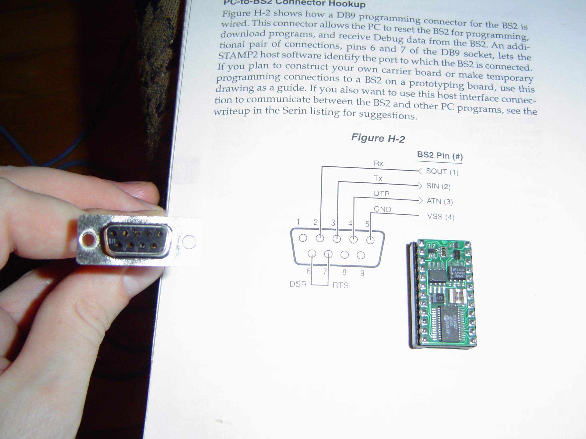
I'm just preparing my pc connection for my bs2, getting ready to connect the pins for the serial connection, but I have a question.
Attached is an image of the cable which will be plugged INTO the pc and a picture of a page from the stamp manual.
my question is, from what perspective is this picture?
for example, in the picture, I am holding the end to go into the pc, should I wire it as shown in the picture in the book, or is it reversed, as if the book is showing the serial port from looking at the back of the PC perspective.
Thanks
▔▔▔▔▔▔▔▔▔▔▔▔▔▔▔▔▔▔▔▔▔▔▔▔
Johnny
2048 x 1536 - 171K
Comments
Look closely at the plug. the numbers are printed in the plastic. You can even see them in the photo you sent.
Kind regards from Kwa Dukuza
John Bond
And that is the right end DB9F (female) that will normally connect in to PC serial ports.·
Is it the other end you can't fit in?· The other end should be a DB9M (male) connector for the stamp board.
Are any pins bent on your PC port?· Are you sure it's the proper one (are you using a laptop; newer laptops don't have serial ports and you might be trying to connect in to the video port which wouldn't work).
▔▔▔▔▔▔▔▔▔▔▔▔▔▔▔▔▔▔▔▔▔▔▔▔
·
Steve
http://members.rogers.com/steve.brady
"Inside each and every one of us is our one, true authentic swing. Something we was born with. Something that's ours and ours alone. Something that can't be learned... something that's got to be remembered."
I interfaced without them and everything appeared to work fine (i.e. I could download a progam into the stamp and run it) The problem was discovered whenever I rebooted the compter while the stamp was still connected with the serial cable. The program would reset and just hang there until I opened the basic stamp editor and then it would start running again.
Bottom line, get the caps, they are cheap and will save you some grief.
Luke
Unfortunatly it is not detecting the type of bs2.
▔▔▔▔▔▔▔▔▔▔▔▔▔▔▔▔▔▔▔▔▔▔▔▔
Johnny
Your picture of the plug in your left hand·is showing the Front (outside) therefore pin 1 would be the upper right pin.
In other words PIN 23 needs to be connected to system ground (the common ground on your carrier board).
If you built your own 5 volt regulator on to the carrier board then connect your regulated voltage between 4.5 Volts and 5.5 volts to PIN 21. Otherwise connect uregulated power between 5.5 and 15 Volts dc to PIN 24. This will then internally regulate the voltage to 5 volts.
Luke