

Auto Navigating Robotic vehicle Using Basic Stamp BS2 basic Kit
 gadgetpatel
Posts: 1
gadgetpatel
Posts: 1
I have a video for my work, please do click the link to have a look at it: DEMO VIDEO LINK
Please Click this alternate link incase the above link does not work : ALTERNATE DEMO VIDEO LINK
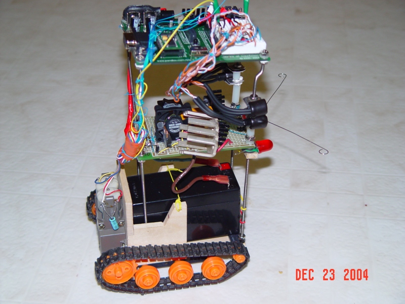
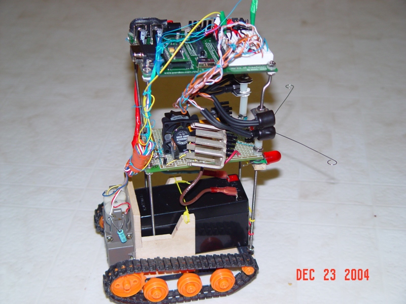
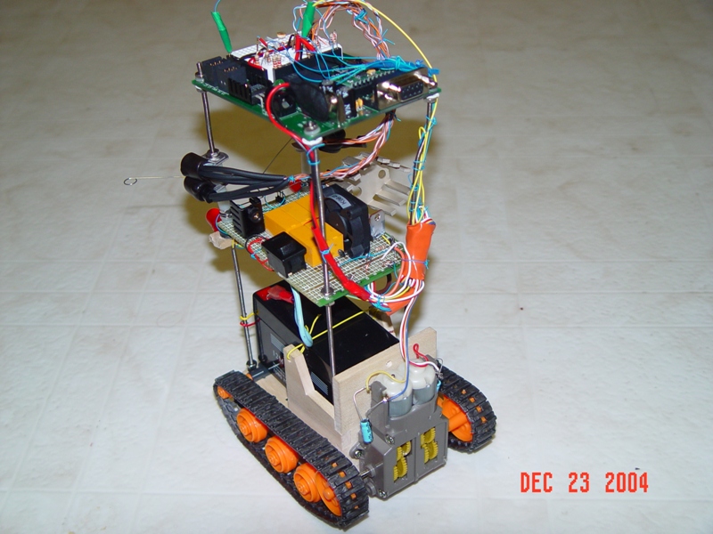
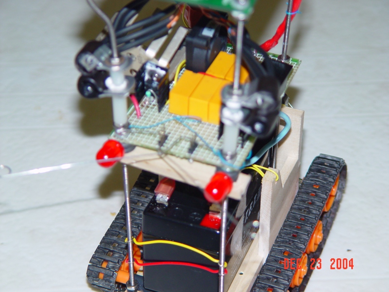
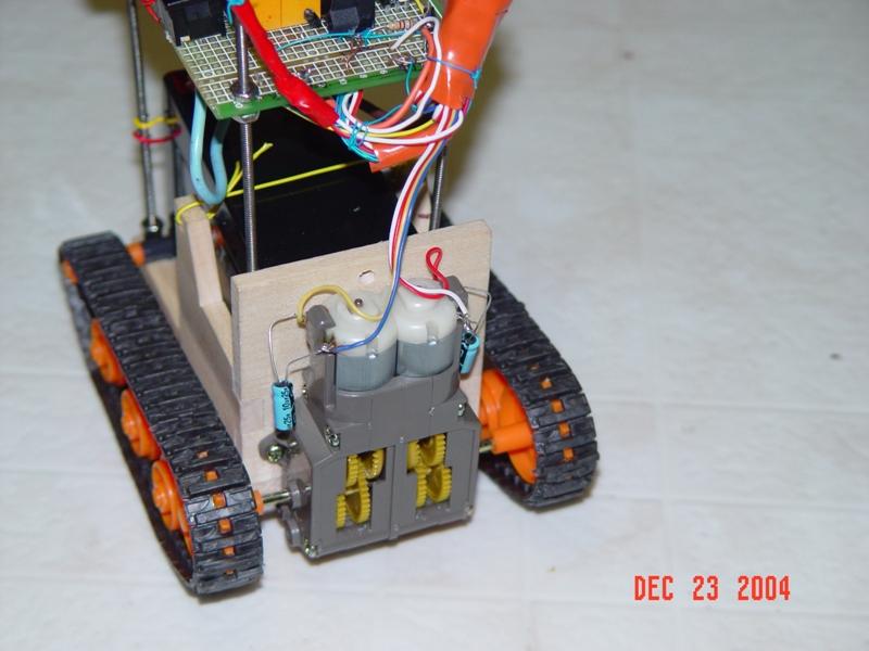
Well the specialty of my work is that except for the basic stamp nothing lese was ready made, I have made it bit by bit, It navigates using the infrared sensors and the Boe-bot Whisker technique, earlier instead of the whiskers and the infrared led and sensors I tried an ultrasonic sensor, but did not fair well.It was then that I decided to go for the Infrared sensors, but they too did not sense any Black plastics like my Dish washer door, and so I was compelled to use the whiskers. I USE a 12 V battery and the 3 pin regulators (7809, 7805 and LM317) to power the basic stamp and the motors (3v each). The output pins of the Basic stamp directly drive three 5 volts relay (one each to drivw the left and right Motors and the third one for forward & reversing using a DPDT relay to change the polarity of the motor), actually you would see five…relays but as of now 2 of them are un-used, I had intended them to use with some other sensors. The only other fancy sensor is the LDR which gives High/Low to a pin and depending on that I light up the red led headlights.
I was having some problems when I initially implemented the infrared sensors, after 4-5 minutes,The basic stamp would go to a no-return state…I tried every thing, and found out that if I disconnect the motors everything is fine and that’s how, I found that since, the Motor and the basic stamp all share the same ground the small sparks inside the motor are causing interference, and that is causing the Basic stamp to behave abnormal, I should have gone for a bipolar capacitor but did not have one so went ahead and used a 10uf 25 volt which I had spare, one each to the motor ends, and that was it…all smooth.
Chanda Rani Patel ( Chanda Patel )
&
Shrimant Patel
http://patelplanet.com
Post Edited (gadgetpatel) : 12/30/2004 3:27:27 AM GMT
Please Click this alternate link incase the above link does not work : ALTERNATE DEMO VIDEO LINK
Well the specialty of my work is that except for the basic stamp nothing lese was ready made, I have made it bit by bit, It navigates using the infrared sensors and the Boe-bot Whisker technique, earlier instead of the whiskers and the infrared led and sensors I tried an ultrasonic sensor, but did not fair well.It was then that I decided to go for the Infrared sensors, but they too did not sense any Black plastics like my Dish washer door, and so I was compelled to use the whiskers. I USE a 12 V battery and the 3 pin regulators (7809, 7805 and LM317) to power the basic stamp and the motors (3v each). The output pins of the Basic stamp directly drive three 5 volts relay (one each to drivw the left and right Motors and the third one for forward & reversing using a DPDT relay to change the polarity of the motor), actually you would see five…relays but as of now 2 of them are un-used, I had intended them to use with some other sensors. The only other fancy sensor is the LDR which gives High/Low to a pin and depending on that I light up the red led headlights.
I was having some problems when I initially implemented the infrared sensors, after 4-5 minutes,The basic stamp would go to a no-return state…I tried every thing, and found out that if I disconnect the motors everything is fine and that’s how, I found that since, the Motor and the basic stamp all share the same ground the small sparks inside the motor are causing interference, and that is causing the Basic stamp to behave abnormal, I should have gone for a bipolar capacitor but did not have one so went ahead and used a 10uf 25 volt which I had spare, one each to the motor ends, and that was it…all smooth.
Chanda Rani Patel ( Chanda Patel )
&
Shrimant Patel
http://patelplanet.com
Post Edited (gadgetpatel) : 12/30/2004 3:27:27 AM GMT
800 x 600 - 215K
800 x 600 - 215K
800 x 600 - 214K
800 x 600 - 209K
800 x 600 - 51K
Comments
very cool to see it in action!!