

How to - Accelerometer (1) Fundamentals and Tilt Measurement
 Andy Lindsay (Parallax)
Posts: 1,919
Andy Lindsay (Parallax)
Posts: 1,919
Getting Started with an Accelerometer
Acceleration is a measure of how quickly speed changes.· Just as a speedometer is a meter that measures speed, an accelerometer is a meter that measures acceleration.· You can use the ability to sense acceleration to measure a variety of things that are very useful to electronic and robotic projects and designs:
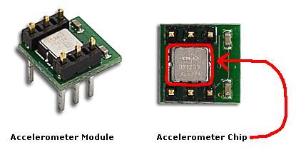
This module measures less than 1/2” X 1/2” X 1/2”, and the accelerometer chip itself is less than 1/4” X 1/4” X 1/8”.

People naturally sense acceleration on three axes, forward/backward, left/right and up/down.· Just think about the last time you were in the passenger seat of a car on a hilly and curvy road.· Forward/backward acceleration is the sensation of speeding up and slowing down.· Left/right acceleration involved making turns, and up down acceleration is what you felt going over hills.·
Up/down acceleration is also the way we sense gravity.· When on the ground, people tend to sense gravity as their own weight.· In free-fall, they sense gravity as weightlessness.· In physics terms, gravity is a form of acceleration.· When an object is on the ground, gravity is sometimes called static acceleration.· When an object is rolling down hill or falling, gravity becomes dynamic acceleration.
Instead of the three axes people sense, the MX2125 accelerometer senses acceleration on two axes.· The acceleration it senses depends on how it’s positioned.· By holding it one way, it can sense forward/backward and left/right.· If you hold it a different way, it can sense up/down and forward/backward.
The MX2125 Accelerometer – How it Works
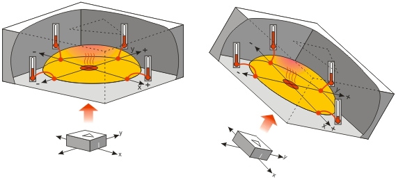
The MX2125’s design is amazingly simple.· It has a chamber of gas with a heating element in the center and four temperature sensors around its edge.· Just as hot air rises and cooler air sinks, the same applies to hot and cool gasses.· If you hold the accelerometer still, all it senses is gravity.· When you hold the accelerometer level, the hot gas pocket is rises to the top-center of the accelerometer’s chamber, and all the temperature sensors measure the same temperature.· Depending on how you tilt the accelerometer, the hot gas will collect closer to one or maybe two of the temperature sensors.·

Both static acceleration (gravity and tilt) and dynamic acceleration (like taking a ride in a car) are detected by the temperature sensors.· If you take the accelerometer for a car ride, the hotter and cooler gasses slosh around in the chamber in a manner similar to a container that is partially filled with water.·
In most situations, making sense out of these measurements is a simple task thanks to the electronics inside the MX2125.· The MX2125 converts the temperature measurements into signals that are easy for the BASIC Stamp® module to measure and decipher.
Connecting and Testing the MX2125
ü······ Gather the parts listed here, and build the circuit shown below.
Parallax
Part Number···· ·Quantity··· ··Description
800-00016·············· (1)········ ··3-inch Jumper wires - bag of 10
150-02210·············· (2)········ ··Resistor – 220
28017····· ··············· (1)········ ··Memsic MX2125 Dual-Axis Accelerometer

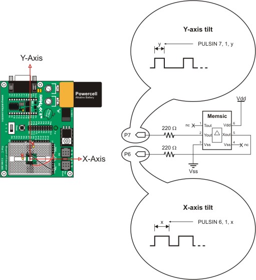
The two axes the MX2125 uses to sense gravity and acceleration are labeled X and Y.· It will help if you set your board flat on the table in front of you as shown in the figure below.· That way, the X and Y axes point the same directions they do on an XY plot.· For room temperature testing, you can get a decent indication of tilt by just measuring the high times of the pulses sent by the MX2125’s Xout and Yout pins with the PULSIN command.· Depending on how far you tilt the board and in which direction, the PULSIN time measurements should range from 1875 to 3125.· When the board is level, the PULSIN command should store values in the neighborhood of 2500.·

ü······ Make sure your board is sitting flat on the table, oriented with its X and Y axes as shown in the figure above.
ü······ Enter and run SimpleTilt.bs2.
' SimpleTilt.bs2
' Measure room temperature tilt.
·
'{$STAMP BS2}
'{$PBASIC 2.5}
·
x·········· ···VAR···· Word
y············· VAR···· Word
·
DO
·
· PULSIN 6, 1, x
· PULSIN 7, 1, y
·
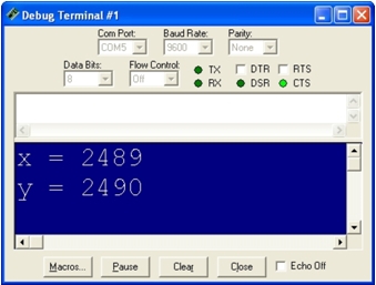
· DEBUG CLS, ? X, ? Y
·
· PAUSE 100
·
LOOP
ü······ Check to make sure the Debug Terminal reports that the x and y variables are both storing values around of 2500.

ü······ Grab the edge of the board with the Y-Axis label and gradually lift it toward you.· The y value should increase as you increase the tilt.·
ü······ Tilt the board straight up and down.· The Debug Terminal should report that the y variable stores a value near 3125.
ü······ Next, instead of tilting the board toward you, gradually tilt it away from you.· The y axis value should drop below 2500 and gradually decrease to 1875 as you tilt the board until it’s straight up and down.
ü······ Repeat this test with the X-axis.· As you tilt the board up with your right hand, the x value should increase and reach a value near 3125 when the board is vertical.· As you tilt the board upward with your left hand, the x value should approach 1875.
ü······ Finally, hold your board in front of you, straight up and down like a steering wheel.
ü······ As you slowly rotate your board, the x and y values should change.· These values will be used in another activity to determine the rotation angle in degrees.
___________________________________________________________________
·
This draft material is part of a forthcoming Stamps in Class text by Andy Lindsay.
·
(c) 2004·by Parallax Inc - all rights reserved.···
Post Edited By Moderator (Jessica Uelmen (Parallax)) : 8/25/2010 5:34:00 PM GMT
Acceleration is a measure of how quickly speed changes.· Just as a speedometer is a meter that measures speed, an accelerometer is a meter that measures acceleration.· You can use the ability to sense acceleration to measure a variety of things that are very useful to electronic and robotic projects and designs:
- Acceleration (of course!)
- Tilt, tilt angle
- Incline
- Rotation
- Vibration
- Collision detection
- Gravity
- Self balancing robots
- Tilt-mode game controllers
- Model airplane auto pilot
- Car alarm systems
- Crash detection/airbag deployment
- Human motion monitoring
- Leveling tool
This module measures less than 1/2” X 1/2” X 1/2”, and the accelerometer chip itself is less than 1/4” X 1/4” X 1/8”.
People naturally sense acceleration on three axes, forward/backward, left/right and up/down.· Just think about the last time you were in the passenger seat of a car on a hilly and curvy road.· Forward/backward acceleration is the sensation of speeding up and slowing down.· Left/right acceleration involved making turns, and up down acceleration is what you felt going over hills.·
Up/down acceleration is also the way we sense gravity.· When on the ground, people tend to sense gravity as their own weight.· In free-fall, they sense gravity as weightlessness.· In physics terms, gravity is a form of acceleration.· When an object is on the ground, gravity is sometimes called static acceleration.· When an object is rolling down hill or falling, gravity becomes dynamic acceleration.
Instead of the three axes people sense, the MX2125 accelerometer senses acceleration on two axes.· The acceleration it senses depends on how it’s positioned.· By holding it one way, it can sense forward/backward and left/right.· If you hold it a different way, it can sense up/down and forward/backward.
The MX2125 Accelerometer – How it Works
The MX2125’s design is amazingly simple.· It has a chamber of gas with a heating element in the center and four temperature sensors around its edge.· Just as hot air rises and cooler air sinks, the same applies to hot and cool gasses.· If you hold the accelerometer still, all it senses is gravity.· When you hold the accelerometer level, the hot gas pocket is rises to the top-center of the accelerometer’s chamber, and all the temperature sensors measure the same temperature.· Depending on how you tilt the accelerometer, the hot gas will collect closer to one or maybe two of the temperature sensors.·
Both static acceleration (gravity and tilt) and dynamic acceleration (like taking a ride in a car) are detected by the temperature sensors.· If you take the accelerometer for a car ride, the hotter and cooler gasses slosh around in the chamber in a manner similar to a container that is partially filled with water.·
In most situations, making sense out of these measurements is a simple task thanks to the electronics inside the MX2125.· The MX2125 converts the temperature measurements into signals that are easy for the BASIC Stamp® module to measure and decipher.
Connecting and Testing the MX2125
ü······ Gather the parts listed here, and build the circuit shown below.
Parallax
Part Number···· ·Quantity··· ··Description
800-00016·············· (1)········ ··3-inch Jumper wires - bag of 10
150-02210·············· (2)········ ··Resistor – 220
28017····· ··············· (1)········ ··Memsic MX2125 Dual-Axis Accelerometer
The two axes the MX2125 uses to sense gravity and acceleration are labeled X and Y.· It will help if you set your board flat on the table in front of you as shown in the figure below.· That way, the X and Y axes point the same directions they do on an XY plot.· For room temperature testing, you can get a decent indication of tilt by just measuring the high times of the pulses sent by the MX2125’s Xout and Yout pins with the PULSIN command.· Depending on how far you tilt the board and in which direction, the PULSIN time measurements should range from 1875 to 3125.· When the board is level, the PULSIN command should store values in the neighborhood of 2500.·
ü······ Make sure your board is sitting flat on the table, oriented with its X and Y axes as shown in the figure above.
ü······ Enter and run SimpleTilt.bs2.
' SimpleTilt.bs2
' Measure room temperature tilt.
·
'{$STAMP BS2}
'{$PBASIC 2.5}
·
x·········· ···VAR···· Word
y············· VAR···· Word
·
DO
·
· PULSIN 6, 1, x
· PULSIN 7, 1, y
·
· DEBUG CLS, ? X, ? Y
·
· PAUSE 100
·
LOOP
ü······ Check to make sure the Debug Terminal reports that the x and y variables are both storing values around of 2500.
ü······ Grab the edge of the board with the Y-Axis label and gradually lift it toward you.· The y value should increase as you increase the tilt.·
ü······ Tilt the board straight up and down.· The Debug Terminal should report that the y variable stores a value near 3125.
ü······ Next, instead of tilting the board toward you, gradually tilt it away from you.· The y axis value should drop below 2500 and gradually decrease to 1875 as you tilt the board until it’s straight up and down.
ü······ Repeat this test with the X-axis.· As you tilt the board up with your right hand, the x value should increase and reach a value near 3125 when the board is vertical.· As you tilt the board upward with your left hand, the x value should approach 1875.
ü······ Finally, hold your board in front of you, straight up and down like a steering wheel.
ü······ As you slowly rotate your board, the x and y values should change.· These values will be used in another activity to determine the rotation angle in degrees.
___________________________________________________________________
·
This draft material is part of a forthcoming Stamps in Class text by Andy Lindsay.
·
(c) 2004·by Parallax Inc - all rights reserved.···
Post Edited By Moderator (Jessica Uelmen (Parallax)) : 8/25/2010 5:34:00 PM GMT
415 x 210 - 16K
569 x 259 - 69K
339 x 257 - 49K

511 x 558 - 47K
Comments
The pdf with the specifications on the Parallax store doesn't seem to use those 220 resistors.
I don't know much about circuits so the wiring diagram will help me a lot when I get the accelerometer in the mail!
Thanks,
LK
http://science.howstuffworks.com/gyroscope3.htm
It talks about gyros for inertial navigation systems.· It's part of a series of pages that starts with
http://science.howstuffworks.com/gyroscope.htm
and ends with
http://science.howstuffworks.com/gyroscope4.htm
I have started playing with freescale semiconductor's 3-axis·accelerometer MMA7260Q
One thing that bugs me is the fact that·I'm not·able to determine tilt of the sensor if I'm·in an elevator or on a train or car for that matter , because of the acceleration associated with them. Correct me if I'm wrong but if you tilt the sensor to say 30deg and you have a horizontal acceleration , the sensor will indicate·say +-0.7g Z-axis and +-0.3g X-axis , depending on the horizontal acceleration. And you won't be able to know what tilt is unless you know the true horizontal acceleration.
Anybody have any idea how to determine tilt when other acceleration (like horizontal) is also experienced??
Thanks
BN
▔▔▔▔▔▔▔▔▔▔▔▔▔▔▔▔▔▔▔▔▔▔▔▔
·1+1=10
Post Edited (Paul Baker) : 12/12/2005 4:01:04 PM GMT
Having 2 sensors that are offset from each other...
Have them offset about 45deg apart in whichever plane and you could get the idea....maybe 90deg apart for easier math!
So....basically an X,Y sensor and then toss in another one for Z measurements (so it'd basically be mounted on end).
As you tilt in one direction, the Z sensor will start to show a horizontal profile as opposed to its bottomed out verticle measurement....
▔▔▔▔▔▔▔▔▔▔▔▔▔▔▔▔▔▔▔▔▔▔▔▔
·
Steve
"Inside each and every one of us is our one, true authentic swing. Something we was born with. Something that's ours and ours alone. Something that can't be learned... something that's got to be remembered."
Here's a link to an article that explains the aeronautical setups nicely and has good terms for more further searches: http://www.bookrags.com/sciences/astronomy/flight-control-spsc-03.html
Post Edited (Andy Lindsay (Parallax)) : 2/3/2006 10:09:51 PM GMT
Thanks for the excellent posts - I'm finally getting somewhere with my MEMSIC2125 now [noparse]:)[/noparse]
I don't know if you can help?! I understand that the MEMSIC, being a 2-axis part, can be used tilted at 45deg and then readings of the two axes combined to get platform angle - even when the platform is moving. MEMESIC's datasheet suggests the formula is 'angle = ACos( 0.707 * (Ax + Ay) / g)', but I'm getting changing angles whenever I move the platform (including if I 'roll' the platform).
I'm probably missing something, but is there any code that gives me what I'm looking for?
Regards,
Simon
I'll have to Google then, as my application doesn't have any non-tilting platform [noparse]:([/noparse]
Cheers,
Simon
The first diagram accompanies the educational curriculum (Stamps in Class) - the books written by Andy. The bottom picture is from our product documentation, also available from download. Use the Stamps in Class diagram.
Ken Gracey
Although I have my answer, it does beg the question as to why the differences...
1. Why the resistors?
2. What does T do?
3. What are the implications of not grounding pin 4?
Again, not that I need answers specifically for my robot... more for just an educational understanding...
1) Stamps in Class materials include resistors in series where wires normally go when the device has outputs that send signals to BASIC Stamp I/O pins. This prevents a problem that can occur if a student builds a new circuit, but leaves the old program running for any length of time. If the old program happens to be sending output-high to a circuit which is sending output-low (or visa-versa), the resistor will protect the BASIC Stamp I/O pin and the device it's connected to.
2) The T pin transmits an analog voltage that indicates the MX2125's internal temperature. This voltage is critical for precision accelerometer applications, which use it to compensate for temperature's effect on pulse widths the MX2125 transmits to report acceleration measurements. There are two kinds of errors this voltage can be used to compensate: zero bias offset and sensitivity. Zero bias offset error is the difference between the zero g pulse width (5 ms) and the actual 0 g pulse width. Sensitivity error is the difference in pulse width for a given acceleration at temperatures A and B. Here are links to a couple of PDFs with more info:
Memsic Temperature Compensation Appnote: http://www.memsic.com/memsic/pdfs/an-00mx-002.pdf
Memsic MX2125 Product Datasheet: http://www.memsic.com/memsic/data/products/MXD2125G&M/MXD2125G&M.pdf
3) Pins 3 and 4 are connected by traces on the circuit board, and they provide 0 V to the MX2125's ground and its external clock input. One of the pins (3 or 4) has to be grounded, but it doesn't matter which one.
There's an exception to item 3, but it does not apply to Memsic 2125 modules that accompany our educational documentation. The first revision of the Memsic 2125 circuit board had one of the pins connected to the MX2125 chip's optional external clock input, and the other connected to the chip's ground. Both of that module's pins should be grounded since applications can rely on the MX2125’s internal clock. These older modules can be identified because they have no silkscreen on the top, only on the underside. Current modules (the ones with pins 3 and 4 shorted) read Mx2125 on the top and Parallax, Inc. underneath.
▔▔▔▔▔▔▔▔▔▔▔▔▔▔▔▔▔▔▔▔▔▔▔▔
Andy Lindsay
Education Department
Parallax, Inc.
BTW, the Smart Sensors and Applications book just got posted to the web today. The chapter on the Memsic accelerometer has quite a bit of material that has not been previously posted. Likewise with the Ping))) Ultrasonic Rangefinder and the Parallax Serial LCD. The HM55B Compass Module has "some" new material, but not as much since I was more in Stamps in Class mode than I realized while writing the product docs.
Here are some of the·Smart Sensors and Applications links:
Product page: http://www.parallax.com/detail.asp?product_id=28029
Book (PDF): http://www.parallax.com/dl/docs/prod/sic/SmartSensors-v1.0.pdf
Source Code (Zip): http://www.parallax.com/dl/sw/SmartSensorsv1.0code-v1.zip
Another resource to check out for the Memsic accelerometer mounted on a robot would be the Stamps in Class "Mini Projects" page: http://forums.parallax.com/showthread.php?p=560570
The book points to this page for Boe-Bot projects with the Memsic 2525 accelerometer module and Ping))) Ultrasonic Distance Sensor. This page has two Boe-Bot + accelerometer projects:
Boe-Bot® Robot Navigation with Accelerometer Incline Sensing: http://forums.parallax.com/showthread.php?p=522967
A Tilt Radio Controller for Your Boe-Bot: http://forums.parallax.com/showthread.php?p=524063
Hopefully, that'll add to·the weekend's robotic fun. Enjoy!
Regards, Andy
▔▔▔▔▔▔▔▔▔▔▔▔▔▔▔▔▔▔▔▔▔▔▔▔
Andy Lindsay
Education Department
Parallax, Inc.
Post Edited (Andy Lindsay (Parallax)) : 12/22/2006 8:16:35 PM GMT
Thanks much!!!
The accelerometer chapter·features some new and kind of funky integer math techniques for minimizing error propagation while scaling the accelerometer measurements for use with various displays and output devices.··Writing about it was kind of an interesting challenge, so we'll be watching the forum closely for questions (and their answers).···
Also, anyone who's got feedback·and/or recommendations,·feel free to email them directly to editor@parallax.com.·
Happy holidays!
▔▔▔▔▔▔▔▔▔▔▔▔▔▔▔▔▔▔▔▔▔▔▔▔
Andy Lindsay
Education Department
Parallax, Inc.
Help
' which can be simplified to
servoDrive = 1500 - servoDrive
▔▔▔▔▔▔▔▔▔▔▔▔▔▔▔▔▔▔▔▔▔▔▔▔
Andy Lindsay
Education Department
Parallax, Inc.
i recently purchased the accelerometer to play around with.· I am at a bit of a loss as how I can position the device so that
I can make the output correspond to horizontal· rotational accelerations.· I am trying to controll the yaw (rudder) on an rc plane.
·
http://www.dprg.org/projects/2003-01a/
Or, from scratch, start at www.analog.com, and type gyro in the search field. Then, follow the link to iMEMS(R) Gyroscopes.
▔▔▔▔▔▔▔▔▔▔▔▔▔▔▔▔▔▔▔▔▔▔▔▔
Andy Lindsay
Education Department
Parallax, Inc.
That code is for making the output from the Accelerometer get higher and make servo input to get lower (which does help)
but I also need the other way around, as accelerometer gets lower the servo gets higher
I the servos at 750 then with it is tilted the servos move either way
and they are currently going to wrong way
Let's say you want a standard servo's position to adjust proportionally to a Memsic 2125 accelerometer's axis measurements.··The best way to do that is to follow the example in Smart Sensors and Applications Chapter 3, Activity #3.· Here are links to the Smart Sensors and Applications PDF text and product page:
··· PDF text download:· http://www.parallax.com/dl/docs/prod/sic/SmartSensors-v1.0.pdf
··· Product page: http://www.parallax.com/detail.asp?product_id=28029
Applied to·an accelerometer input domain and·a servo output range, your PBASIC command would take this form:
···· servoOutput·=·accelerometerInput·- lowestAccelerometerInput ** scaleConstant + servoOffsetConstant
Let's say your accelerometer's input domain is 1875 to 3125, and the desired servo output range is 300 to 1200.· servoOutput and accelerometerInput are your variables.· lowestAccelerometerInput will be 1875, and servoOffsetConstant will be 300.· So all we need to figure out is the scaleConstant.· Page 77 of Smart Sensors and Applications has a useful equation for figuring out ** scale constants that·minimize potential·integer math offset errors:
·
· ··· ScaleConstant = Int[noparse][[/noparse]65536(output scale elements / (input scale elements - 1))]
·
The input scale is the accelerometer's domain of 1875 to 3125, and the output scale·range is·300 to 1200.· So there are 1251 input domain elements which have to proportionally map to 901 output range elements.· Plug those values into the ScaleFactor equation, and you get:
·
··· ScaleConstant = Int[noparse][[/noparse]65536(901 / (1251-1))] = 47238
·
Now, we have all the values we need for the servoOutput PBASIC command:
·
···' Directly proportional servo output
·· servoOutput = accelerometerInput·- 1875 ** 47238 + 300
·
Now, if you want your range to be 1200 to 300 instead of 300 to 1200, all you have to do is apply the command I posted earlier.· Here's a modified version that uses another variable to make the distinction between the scaled output and the inverted version of the scaled output:
·
·· '·Inversely proportional servo output
···servoOutputInverted = 1500 - servoOutput
·
Andy··
▔▔▔▔▔▔▔▔▔▔▔▔▔▔▔▔▔▔▔▔▔▔▔▔
Andy Lindsay
Education Department
Parallax, Inc.
Post Edited (Andy Lindsay (Parallax)) : 6/7/2007 5:37:59 PM GMT
This is my First big project
I have now already build 3x major projects using these resistors. At times i was getting funny or nun-stable readings, especially from the y-axis for some reason. Lately i have been excluding the resistors. This seems to have a rock sold stability. I have carefully looked over the situation and could not came to a conclusion.
I too would like some feed back on my findings.
I recently bought a parallax MEMSIC 2125 Dual-axis accelerometer. I am trying to get displacement values from the acceleration measurements. I know I could combine the x and y acceleration vectors to get a resultant acceleration vector. But according to the data I have been getting the acceleration is changing over time. How do I go about getting this fundamental data?
Yours Sincerely,
S
▔▔▔▔▔▔▔▔▔▔▔▔▔▔▔▔▔▔▔▔▔▔▔▔
Andy Lindsay
Education Department
Parallax, Inc.
Post Edited (Andy Lindsay (Parallax)) : 7/17/2008 8:13:42 PM GMT
And why the range is set·from 1875 to 3125? Is there a relationship between this and how many bytes of the BS controller or the resolution of the results?
(2) What is the original outputs from MXD2125 and how·does the BS interpret it as some number between 1875 and 3125 and send it to the computer?
(3) I am supposing I can use the PAUSE command to change the sampling rate of getting the X, Y. Where is the result at last sampling time? Does the·microcontroller save it or not?(I mean the controller just erases the previous data and saves the latest data?) Is there a way to export such kind of data? Because I want to do some post process using softwares like Matlab. Only reading the real-time X, Y can't help me in analyzing the motion details of the·object.
I just want to know more about·the inside mechanism.·Appreciate your help!