How to - Amplifying a Piezo Speaker and Volume Control
 Andy Lindsay (Parallax)
Posts: 1,919
Piezospeaker Volume Control
Here is a·activity you can use to control the volume of your Piezospeaker with a potentiometer.· The volume ranges from barely audible to annoyingly loud.·
Parts List
You can find most of these parts in the What's a Microcontroller kit.· The LM358 is part of the Basic Analog and Digital kit, but you can also purchase it online through the Parallax Component Shop.· The 9 V battery clip is an item you can probably get at your local Radio Shack or other electronics outlet.
Parallax
Part Number···· Quantity··· Description
· 152-01031········· (1)········· 10 k potentiometer
· 150-01030···· ···· (2)········· 10 k resistors
············································· or (1) 5 k
· 900-00001········· (1)········· Piezospeaker
· 800-00016········· (misc.)···· Jumper wires
························· (2)········· 9 V batteries
· 602-00015······ ·· (1)········· LM358 opamp
························· (1)········· 9 V battery clip with tinned leads
Amplifier Circuit Between P9 and Piezospeaker
The circuit you are about to build is called an inverting amplifier circuit.· It has an input that receives the audio signal from the BASIC Stamp(R) 2 microcontroller's P9 I/O pin.··It's output is connected to the piezospeaker, and you can control the volume with a potentiometer.··The LM358 in the amplifier circuit·will need a dual power supply, which·you will use two 9 V batteries and·one 9 V battery clip with tinned leads to build.
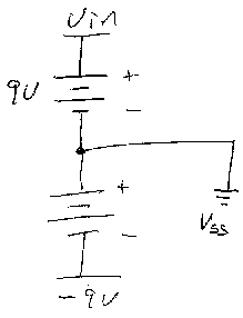
Dual Supply Schematic
To get good amplification with one opamp circuit, the opamp chip can needs two supplies, a negative voltage and a positive voltage.· By plugging a 9 V battery into the Board of Education's battery clip, this will give you + 9 V at the Vin sockets above the breadboard.· If you measure this with a voltmeter, connect the positive lead to Vin and the negative lead to Vss.· To make the -9 V supply, simply connect the positive lead of your second 9 V battery to Vss.· The negative lead will then supply -9 V.· Most 9 V battery clips with tinned leads have a red lead connected to the battery's positive terminal, and a black lead connected to the battery's negative terminal.· Verify this with a voltmeter.· If the red lead is indeed the connected to the 9 V battery's positive terminal, then connect the it to Vss, and set the black lead aside.· You will connect the black lead to the opamp's negative power supply input when you build that circuit.

LM358 Pin Map
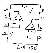
This is a pin map of the LM358 opamp chip.· It has two opamp circuits in it along with a positive and negative power inputs.· Remember to use the semicircle reference notch to get the chip right-side-up on the breadboard.· If you plug it in upside-down but wire it as though it's right-side-up, it could damage the chip and maybe your BASIC Stamp too.

Project Schematic
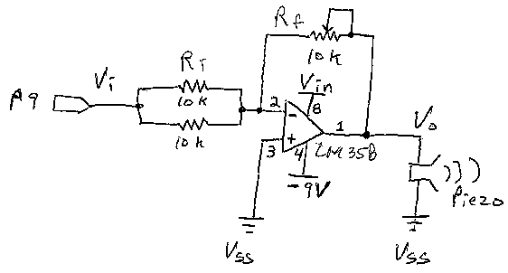
This is the circuit you will need to build.· It's really easy to make a wiring mistake on this kind of circuit; I corrected several before I could get my own circuit to work.· Fortunately for me, I didn't damage anything.· Before you actually plug in the batteries, triple check the circuit.
Note that the opamp triangle in the schematic has pin number references that match the ones on the pin map.· Build this circuit.· You will be using the dual power supply you built earlier, make sure to connect Vin to pin 8 on the LM358, and connect the -9 V (battery clip's black lead) to pin 4 on the LM358.· Vss should be connected to pin 3 on the opamp.·

Wiring Diagram
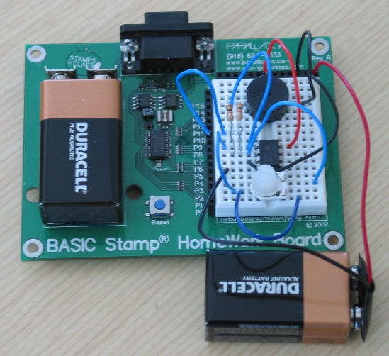
Here is a photo of the completed circuit that you can use as a wiring diagram for trouble-shooting.·

Testing the Circuit
When I plug in my batteries, I usually monitor the opamp's temperature for fifteen or so seconds by resting my fingertip on the top of the chip.· If it gets hot in this amount of time, I disconnect power immediately and start looking for wiring errors.
If your LM358 stays cool, run a program to make your BASIC Stamp generate a ten second tone:
Test Program
I like playing a tone for about ten seconds.· This gives me enough time to turn the pot and verify that it controls volume, but it doesn't go on long enough to disturb·anybody else.· If I want to run the program a second time, I just press and release the Reset button on my board.·
Run this program and verify·that you can control the tone volume with·the potentiometer.· The full range of potentiometer motion should change the volume from quiet to loud, and visa-versa.
How the Circuit Works
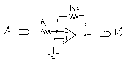
Here is a simplified version of the opamp circuit.· This·circuit is called an inverting opamp circuit.· Vi is the input voltage, Vo is the output voltage, and Ri and Rf are called the input and feedback resistors.· In your circuit, Ri is two 10 k resistors in parallel, for an equivalent resistance of 5 k.· Rf is a 10 k pot, and it can be adjusted anywhere from about 100 ohms·to 10 k.

Opamp is short for operational amplifier.· Here is the math operation that this operational amplifier circuit performs:
Vo = (-Vi * Rf / Ri)
Vo is the inverting amplifier's output voltage, and it is the negative of the input voltage (Vi), scaled by the ratio of the feedback resistor (Rf) divided by the input resistor (Ri).· Keep in mind that you turn the potentiometer to control the value of Rf.· When·the potentiometer is·in the middle of its range of motion, Rf and Ri are both 5000, so Vo is simply the negative of the input voltage.· When Rf is near 10 k, Rf/Ri = 10000/5000 = 2.· So, the output voltage is -2 times the input voltage.· If you turn the potentiometer the other direction, below 5000, to say, 500, then the output voltage is -1/10 of the input voltage.
Your Turn - Digital Potentiometer Control
Try replacing the potentiometer with the digital potentiometer from What's a Microcontroller, Chapter 9.· You can then modify the program to control the volume automatically, or even with the Debug Terminal.
The piezospeaker plays notes loudest at 5 kHz, and the device's response is optimal between 4.5 and 5.5 kHz.· As the notes get lower, they are attenuated by the speaker and they sound quieter.· With a digital potentiometer, the BASIC Stamp can be programmed to automatically adjust the volume of each note so that it compensates for the piezospeaker's tendency to play some notes louder than others.· This is a project that will require some time, experimentation and tuning.· Good luck!
___________________________________________________________________
This draft material is part of a forthcoming Stamps in Class text by Andy Lindsay.
(c) 2004·by Parallax Inc - all rights reserved.··
Post Edited By Moderator (Jessica Uelmen (Parallax)) : 8/25/2010 6:34:21 PM GMT
Here is a·activity you can use to control the volume of your Piezospeaker with a potentiometer.· The volume ranges from barely audible to annoyingly loud.·
Parts List
You can find most of these parts in the What's a Microcontroller kit.· The LM358 is part of the Basic Analog and Digital kit, but you can also purchase it online through the Parallax Component Shop.· The 9 V battery clip is an item you can probably get at your local Radio Shack or other electronics outlet.
Parallax
Part Number···· Quantity··· Description
· 152-01031········· (1)········· 10 k potentiometer
· 150-01030···· ···· (2)········· 10 k resistors
············································· or (1) 5 k
· 900-00001········· (1)········· Piezospeaker
· 800-00016········· (misc.)···· Jumper wires
························· (2)········· 9 V batteries
· 602-00015······ ·· (1)········· LM358 opamp
························· (1)········· 9 V battery clip with tinned leads
Amplifier Circuit Between P9 and Piezospeaker
The circuit you are about to build is called an inverting amplifier circuit.· It has an input that receives the audio signal from the BASIC Stamp(R) 2 microcontroller's P9 I/O pin.··It's output is connected to the piezospeaker, and you can control the volume with a potentiometer.··The LM358 in the amplifier circuit·will need a dual power supply, which·you will use two 9 V batteries and·one 9 V battery clip with tinned leads to build.
Dual Supply Schematic
To get good amplification with one opamp circuit, the opamp chip can needs two supplies, a negative voltage and a positive voltage.· By plugging a 9 V battery into the Board of Education's battery clip, this will give you + 9 V at the Vin sockets above the breadboard.· If you measure this with a voltmeter, connect the positive lead to Vin and the negative lead to Vss.· To make the -9 V supply, simply connect the positive lead of your second 9 V battery to Vss.· The negative lead will then supply -9 V.· Most 9 V battery clips with tinned leads have a red lead connected to the battery's positive terminal, and a black lead connected to the battery's negative terminal.· Verify this with a voltmeter.· If the red lead is indeed the connected to the 9 V battery's positive terminal, then connect the it to Vss, and set the black lead aside.· You will connect the black lead to the opamp's negative power supply input when you build that circuit.
LM358 Pin Map
This is a pin map of the LM358 opamp chip.· It has two opamp circuits in it along with a positive and negative power inputs.· Remember to use the semicircle reference notch to get the chip right-side-up on the breadboard.· If you plug it in upside-down but wire it as though it's right-side-up, it could damage the chip and maybe your BASIC Stamp too.
Project Schematic
This is the circuit you will need to build.· It's really easy to make a wiring mistake on this kind of circuit; I corrected several before I could get my own circuit to work.· Fortunately for me, I didn't damage anything.· Before you actually plug in the batteries, triple check the circuit.
Note that the opamp triangle in the schematic has pin number references that match the ones on the pin map.· Build this circuit.· You will be using the dual power supply you built earlier, make sure to connect Vin to pin 8 on the LM358, and connect the -9 V (battery clip's black lead) to pin 4 on the LM358.· Vss should be connected to pin 3 on the opamp.·
Wiring Diagram
Here is a photo of the completed circuit that you can use as a wiring diagram for trouble-shooting.·
Testing the Circuit
When I plug in my batteries, I usually monitor the opamp's temperature for fifteen or so seconds by resting my fingertip on the top of the chip.· If it gets hot in this amount of time, I disconnect power immediately and start looking for wiring errors.
If your LM358 stays cool, run a program to make your BASIC Stamp generate a ten second tone:
Test Program
I like playing a tone for about ten seconds.· This gives me enough time to turn the pot and verify that it controls volume, but it doesn't go on long enough to disturb·anybody else.· If I want to run the program a second time, I just press and release the Reset button on my board.·
Run this program and verify·that you can control the tone volume with·the potentiometer.· The full range of potentiometer motion should change the volume from quiet to loud, and visa-versa.
' ToneForOpampVolumeTest.bs2

'{$STAMP BS2}
'{$PBASIC 2.5}

DEBUG "Mi...", CR:  FREQOUT 9, 10000, 1319     ' E6

END
How the Circuit Works
Here is a simplified version of the opamp circuit.· This·circuit is called an inverting opamp circuit.· Vi is the input voltage, Vo is the output voltage, and Ri and Rf are called the input and feedback resistors.· In your circuit, Ri is two 10 k resistors in parallel, for an equivalent resistance of 5 k.· Rf is a 10 k pot, and it can be adjusted anywhere from about 100 ohms·to 10 k.
Opamp is short for operational amplifier.· Here is the math operation that this operational amplifier circuit performs:
Vo = (-Vi * Rf / Ri)
Vo is the inverting amplifier's output voltage, and it is the negative of the input voltage (Vi), scaled by the ratio of the feedback resistor (Rf) divided by the input resistor (Ri).· Keep in mind that you turn the potentiometer to control the value of Rf.· When·the potentiometer is·in the middle of its range of motion, Rf and Ri are both 5000, so Vo is simply the negative of the input voltage.· When Rf is near 10 k, Rf/Ri = 10000/5000 = 2.· So, the output voltage is -2 times the input voltage.· If you turn the potentiometer the other direction, below 5000, to say, 500, then the output voltage is -1/10 of the input voltage.
Your Turn - Digital Potentiometer Control
Try replacing the potentiometer with the digital potentiometer from What's a Microcontroller, Chapter 9.· You can then modify the program to control the volume automatically, or even with the Debug Terminal.
The piezospeaker plays notes loudest at 5 kHz, and the device's response is optimal between 4.5 and 5.5 kHz.· As the notes get lower, they are attenuated by the speaker and they sound quieter.· With a digital potentiometer, the BASIC Stamp can be programmed to automatically adjust the volume of each note so that it compensates for the piezospeaker's tendency to play some notes louder than others.· This is a project that will require some time, experimentation and tuning.· Good luck!
___________________________________________________________________
This draft material is part of a forthcoming Stamps in Class text by Andy Lindsay.
(c) 2004·by Parallax Inc - all rights reserved.··
Post Edited By Moderator (Jessica Uelmen (Parallax)) : 8/25/2010 6:34:21 PM GMT


Comments
This is a very nice project. I am new to electronics and have a few questions, if I may ask???? First, I am having trouble locating the LM358. I am going to order one from Parallax; however, I was wondering if I could substitute another IC in its place for the time being? Any idea? LM272 or 386? (I have some of those lying around.) Second, I would like to somehow combine this project with the Christmas Caroling device, to amplify the sound. BUT, I'm not quite sure how to do it. I don't think that there is enough room on the Christmas Caroling STAMP to also build this amp. Is there some way I could combine the two? Or connect two STAMPS? Any ideas for a newbie would be greatly appreciated. Thank you for your help.
Thanks for your response. Radio Shack is just down the street, so I'll pay them a visit today. I'll tell them that you sent me and see if I can get YOU a discount.
Thanks for your help; I appreciate it.
What kind of small speaker should I use, and how would I connect it to the amp chip? Would the connections be like the ones in the activity?
A small, 8 Ohm, dynamic speaker in the 1W range would suffice.
Since the amplifier circuit is powered by a single supply, then a capacitor would need to be inserted between the output of the amp and the speaker to protect the speaker from the DC offset; value of 10uF or more would be sufficient.
I checked Radio Shack's DIY web page and they don't seem to carry simple speakers anymore, so you may have to buy from Mouser, DigiKey, Jameco, etc.
Regards.
I have a set of sony speakers with with an 8ohm impedance and power handling capacity of 0.2W rated and 0.4W max. I do not have a 10uF capacitor, but i do have a 3300uF, a 1000uF, four 0.1uF, and four 0.01uF capacitors. Could these work for this circuit? and if they do, how should they be connected?
The 1000uF will work, put the plus (+) side toward the amplifier output, the other end to the speaker you mentioned.
Lemme know how it works?
***Whoa!!! Wait - are you powering the amp from a single supply, or are you using 2 supplies (+, -)? If you're using 2 supplies, then the coupling cap will not be needed.
There're some tricks that could be done with the LM358, but the better thing to do would be purchase an IC designed to drive a speaker, such as the LM386 (Radio Shack sells these for under $2).
I'm sure other Forum Wizards will have suggestions for low voltage power amps.
There was a previous thread on the Forum where someone was asking about preferences for single-chip power amps; late last year, earlier this year?
One last thing about the LM386...did you set it up for its minimum gain of 20, or for more gain? If the previous .doc schematic referenced the 386, then it would appear that it was set to 20.
http://www.radioshack.com/product/index.jsp?productId=2062620
I looked through the RS site and could not find that little beauty. It was my initial thought for NB, but since I wasn't able to find it, couldn't pass on the info.
Thanks erco!
-Phil
Chopped liver & BestBuy netbooks: http://www.seriouseats.com/recipes/2010/03/the-nasty-bits-chopped-liver-recipe.html
THAT was funny!!
I still hate liver, though.
Also can this be supplied with a 12v power supply?
Thanks
-Phil
I have all the parts, however my op amp and potentiometer are different from your example.
My OpAmp is this (it doesn't have the semicircle..): http://thumbs3.ebaystatic.com/d/l225/m/mecIGU9IUhQGLXSWqCauqmg.jpg
My 10K Potentiometer is this: http://www.source-electronics.co.uk/RadioShack-10K-Ohm-Mini-Volume-Control
Also instead of a Piezzo Speaker I am using a regular Speaker on pin9 and Gnd on the Arduino board.
Any thoughts on how to hook it up?
Thanks a lot in advance!!
Do you have the datasheet for the AD290 you're using?
Also, quick question about the potentiometer. Why are the bottom and middle terminals connected? Doesn't that not do anything since you only need it as a variable resistor (2 terminals connected). Don't understand why that extra wire is there.