

controlling a continuous voltage via bs2
 polram
Posts: 7
polram
Posts: 7
Hello Forum.
I would like to know if this is possibe via the bs2 stamp: Any suggestions would be greatly appreciated...
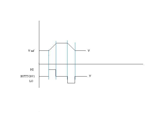
The requirement is for 2 inputs controlling a single, continuous output.
For example:
If a signal is given to input high via a momentary/manual switch at Vref,
then the voltage increases as long as the momentary switch is held. As soon
as the switch is released, that final voltage magnitude is maintained.
Now, if the signal is given to input low via the momentary/manual switch,
then the voltage decreases as long as the momentary switch is held. As soon
as the switch is released, that final voltage magnitude is maintained.
This final voltage magnitude needs to be "indefinite". Meaning, if I left it set at like 7VDC,
I can come back 2 weeks later and change those 7VDC.
How can I use the bs2 to help me keep this voltage maintained without degrading?
The minimum voltage range is +/- 10VDC.
Use the graph attached for operation reference.
Thank you so much,
Regards,
polram
I would like to know if this is possibe via the bs2 stamp: Any suggestions would be greatly appreciated...
The requirement is for 2 inputs controlling a single, continuous output.
For example:
If a signal is given to input high via a momentary/manual switch at Vref,
then the voltage increases as long as the momentary switch is held. As soon
as the switch is released, that final voltage magnitude is maintained.
Now, if the signal is given to input low via the momentary/manual switch,
then the voltage decreases as long as the momentary switch is held. As soon
as the switch is released, that final voltage magnitude is maintained.
This final voltage magnitude needs to be "indefinite". Meaning, if I left it set at like 7VDC,
I can come back 2 weeks later and change those 7VDC.
How can I use the bs2 to help me keep this voltage maintained without degrading?
The minimum voltage range is +/- 10VDC.
Use the graph attached for operation reference.
Thank you so much,
Regards,
polram
640 x 512 - 13K
Comments
▔▔▔▔▔▔▔▔▔▔▔▔▔▔▔▔▔▔▔▔▔▔▔▔
Sid Weaver
Try the Stamp Tester
http://hometown.aol.com/newzed/index.html
·
What you are asking for shouldn't be too hard. Here is one possibility. You would set up a counter on the Stamp and monitor the two switches for "up" and "down". When the Stamp detects that one of the switches is activated it would either increase or decrease the counter value accordingly. Each time the counter value is changed you would send the new value to a DAC. The DAC output would have to be conditioned with an op-amp to scale and offset it to realize a +-10V excursion.
Now for the nitty gritty stuff. You will have to decide the resolution per change and pick the DAC accordingly. Also, the rate of change as the switch is held down will have to be considered. If the Stamp is running at full rpm, the entire range could be covered before you let go of the switch.
You will need to a little math such that the minimum output from the DAC will be -10V and the maximum will represent +10V.
By nature the value you set will stay there forever as long as power is applied. For extra measure, you could put the setting in EEPROM in case of a power failure.
Hope this helps.
Lee Harker
polram
Here's an idea for the code:
Set_Voltage:
· DO
··· IF (level < 255) THEN········· ' check for max value
····· level = level + IncVolts
··· ENDIF
··· IF (level > 0) THEN
····· level = level - DecVolts···· ' check for min value
··· ENDIF
· PWM PwmPin, level, 50
· LOOP
The (active-high) buttons get scanned and the output updated every 50 milliseconds.
▔▔▔▔▔▔▔▔▔▔▔▔▔▔▔▔▔▔▔▔▔▔▔▔
Jon Williams
Applications Engineer, Parallax
Dallas Office
If I may ask, what are you trying to drive with the +-10volts at 0.5 amps? And what
resolution do you require?
A linear output stage that can handle 0.5 amps will probably require a power op amp
and some sort of heat sink.
Dave G
This is en elctro-mechanical application, part of a bigger circuit. I do need to drive part of a motor assembly. Yes, you are correct, I will need to incorporate a power gain circuit.
Here is another possibility I am investigating:
How easy will it be turn the stamp into a 1Hz oscillator?
P.
One_Hertz:
· TOGGLE Outpin
· PAUSE 500
· GOTO One_Hertz
▔▔▔▔▔▔▔▔▔▔▔▔▔▔▔▔▔▔▔▔▔▔▔▔
Jon Williams
Applications Engineer, Parallax
Dallas Office
I believe the BS2 will be accurate +- 10% or so -- which isn't very accurate, really.
PAUSE 0
will give you about 100 microsecond pause
▔▔▔▔▔▔▔▔▔▔▔▔▔▔▔▔▔▔▔▔▔▔▔▔
Jon Williams
Applications Engineer, Parallax
Dallas Office