

LTC1298 12-bit A/D converter DIP
 yzche
Posts: 35
yzche
Posts: 35
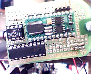
I use converters on a prototying board and a bread board. Converters show different result on different board.·I attached pictures of them on the bread board and prototying board.
on prototyping board with wire wrap socket:
channel 1: 253
channel 0: 266
channel 1: 260
channel 0: 279
channel 1: 254
channel 0: 276
(I need to measure voltage of battery and I need·to connect wire to pin of converter first. After I connect wire to the pin,without battery, voltage went up)
channel 1: 1808
channel 0: 1200
channel 1: 1100
channel 0: 1032
on bread board:
channel 1: 100
channel 0: 120
channel 1: 107
channel 0: 125
channel 1: 109
channel 0: 138
(after touching wire, nothing happen)
channel 0: 120
channel 1: 107
channel 0: 125
channel 1: 109
channel 0: 138
Anyone knows why. · Anyway to fix it?
on prototyping board with wire wrap socket:
channel 1: 253
channel 0: 266
channel 1: 260
channel 0: 279
channel 1: 254
channel 0: 276
(I need to measure voltage of battery and I need·to connect wire to pin of converter first. After I connect wire to the pin,without battery, voltage went up)
channel 1: 1808
channel 0: 1200
channel 1: 1100
channel 0: 1032
on bread board:
channel 1: 100
channel 0: 120
channel 1: 107
channel 0: 125
channel 1: 109
channel 0: 138
(after touching wire, nothing happen)
channel 0: 120
channel 1: 107
channel 0: 125
channel 1: 109
channel 0: 138
Anyone knows why.
· Anyway to fix it? 
352 x 288 - 24K
352 x 288 - 27K
Comments
One way to reduce the voltage fluctuations is to lower the effective input impedance.· You can do this by connecting a resistor from the input to ground - the smaller the better for noise reduction but if you make it too small, it will load the circuit that you're trying to sample.· The value that you choose will depend on what's driving it.· If you're sampling a battery voltage, you'll want to choose the resistor so that the current it draws from the battery is small enough to be tolerable.
Another way to reduce the noise on the A/D input is to place a capacitor between the input and ground.· A capacitor looks like a low resistance to higher frequency AC signals but is an open circuit (in steady state) to DC signals.· The drawback to using a capacitor is that it reduces the ability to track a rapidly changing signal.· If you're sampling a battery, that is probably not a problem at all as the battery voltage will not likely be changing very fast.· You can imagine, though, that with some other signals, you would not want to add very much capacitance to the A/D input.
As a starting point, you might want to try a 1uF capacitor and see how it affects your results.· Then, change it to a higher or lower value and check again.
▔▔▔▔▔▔▔▔▔▔▔▔▔▔▔▔▔▔▔▔▔▔▔▔
Don Kinzer
·
Simply connect one end of the POT to Ground, the other end to VCC (if that's your voltage input range) and the wiper lead to the input of the A/D converter.· If you have any questions I will get you a schematic.
▔▔▔▔▔▔▔▔▔▔▔▔▔▔▔▔▔▔▔▔▔▔▔▔
Chris Savage
Knight Designs
324 West Main Street
P.O. Box 97
Montour Falls, NY 14865
(607) 535-6777
Business Page:·· http://www.knightdesigns.com
Personal Page:··· http://www.lightlink.com/dream/chris
·
If you mean my comment about the POT, no, I meant like the attached schematic...
▔▔▔▔▔▔▔▔▔▔▔▔▔▔▔▔▔▔▔▔▔▔▔▔
Chris Savage
Knight Designs
324 West Main Street
P.O. Box 97
Montour Falls, NY 14865
(607) 535-6777
Business Page:·· http://www.knightdesigns.com
Personal Page:··· http://www.lightlink.com/dream/chris
There is no free lunch. Low current draw requires high input impedance which results in higher noise susceptibility.
Another option, of course is to add a shielding around your circuit. Search for "Faraday Cage".
▔▔▔▔▔▔▔▔▔▔▔▔▔▔▔▔▔▔▔▔▔▔▔▔
Don Kinzer
·