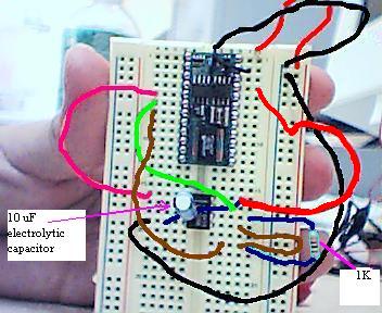
LTC1298 12-bit A/D converter DIP
I try to use ·LTC1298 12-bit A/D converter DIP and here are my outputs.
channel 0: 109
channel 1: 186
channel 0: 104
channel 1: 72
channel 0: 100
channel 1: 117
channel 0: 99
channel 1: 112
channel 0: 101
channel 1: 111
channel 0: 103
channel 1: 108
channel 0: 103
channel 1: 155
only problem is that I did not put any input voltage for converter to convert. I thought each channel should returns 0 when there is no input voltage. I attached a picture of my bread board, I might have wrong wiring.


Comments
Connect the input to ground if you want zero's.
Terry
channel 0: 0
channel 1: 1
channel 1: 0
channel 0: 0
channel 1: 1
channel 0: 0
channel 1: 1
I don't understand why both channels are affected. I thought each channel is independent.
Do you know what mode you are running in?
If you leave one of the inputs floating and hook up a wire and a piece of aluminum foil suspended on it, you can have fun watching the reading change as you wave your hand near the foil "capacitor" plate. Your hand is the other "plate" in relation to the static electric field that exists in your space. (Don't touch the plate if you have been shuffling across the carpet!--that static flash might well burn out the input channel of the LTC1298!!!!!)
Now, if you attach the second input to a solid voltage, say 1.5 volts, you should get a good reading. The low impedance of your voltage source dominates the leakage currents and the effects of coupling capacitance, which are very (usually!) very small.
The same thing applies to the input pins of the BASIC Stamp itself. If you leave all the pins as inputs, and then connect one of them to +5 volts, you may well observe that that all of them, the neighboring pins especially, will also read high. Here is the fun program:
DO : DEBUG BIN16 INS, CR : LOOP
If you connect one pin to Vss instead, then all the neighboring pins will read low, at least for a while, until some other influence causes them to drift away. The effect is especially strong on those white plug-in breadboards, because the capacitance between neighboring nodes is so high.
-- Tracy
▔▔▔▔▔▔▔▔▔▔▔▔▔▔▔▔▔▔▔▔▔▔▔▔
Tracy Allen
www.emesystems.com