

Glass scale measurements
 ManAtWork
Posts: 2,365
ManAtWork
Posts: 2,365
I just implemented the processing of Sine/Cosine signals of Heidenhain glass scale. The scale outputs two quadrature signals that are 90° phase shifted just like from an encoder. But the signals are no square waves but instead analogue sin/cos signals with a period of 20µm.
In this video you can see the signals plotted into a SCOPE_XY debug window. As the sensor head of the scale moves the green dot rotates in a circle. Instead of only counting full quadrants like with a standard encoder the position can be interpolated down to 5nm resolution. The arctan computation to get the angle from the sine and cosine values is simple on the P2 and can be done with a single QVECTOR instruction.
However, I've invested quite some work to get the offset and gain correction right. The signals have a nominal amplitude of 1V peak-peak but can get as low as 0.6V with an offset up to 0.3V. Channel to channel matching can also vary between 0.8 and 1.25 meaning that the circle could be distorted to an ellipse without automatic correction. Offset and gain can not only vary between different devices but even from one end to the other on the same scale. Temperature drift and frequency dependant changes (low pass filtering) can make it worse.
The red dot shows the offset. In the video it barely moves but you could see the changes if I moved the head from end to end on the scale.
Comments
That's in micron!? Very cool.
Is the compensation all done in software? And using the built-in Prop2 ADC hardware? Or is it all external?
I remember you posting this (Which has no external adjustments) - https://forums.parallax.com/discussion/comment/1573240/#Comment_1573240
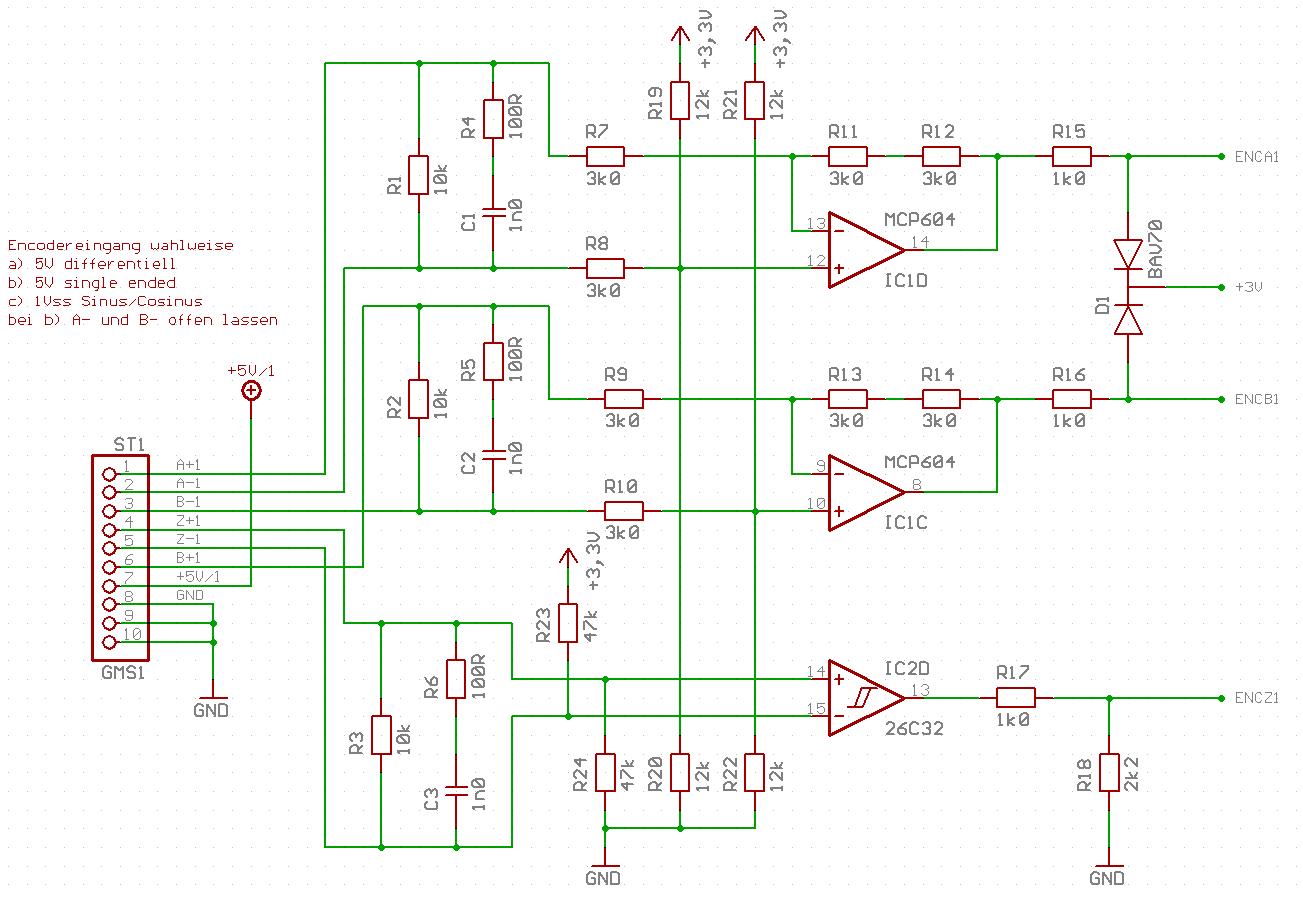
Yes, exactly. I only use those gain=2 differential pre-amplifiers. If you want to trade some smart pis for external components it would also be possible to use 6 instead of 3 pins and do the differentiation in software.
The automatic gain and offset adjustment works like this:
Sample value sin/cos pairs are stored into 16 bins according to their polar coordinate calculated with the current offset adjustment. For example angles 0..22.5° are put into bin 0, 22.5..45° into bin 1 and so on. The points are then rotated to the center point (11.25° for bin 0) of each bin so that they "pull" the center point equally when averaged. This center point is taken as the next offset after
low-pass filtering to reduce noise.
The weighted average of the X coordinates of each bin is used for the gain adjustment of the cosine signal and the weighted average of the Y coordinates for the sine signal.
This algorithm is relatively complex but performs better than a simple "average of min/max" approach as it's quite close to a "best fit circle search" and less sensitive to noise or distortion effects.