

A Stepper Motor. Some Measurements and a Model for LTSpice
 Christof Eb.
Posts: 1,598
Christof Eb.
Posts: 1,598
As P2 is well suited for control jobs with step motors, this might perhaps be interesting for others here?
Idea was and is to learn more about step motors and their behaviour. I have been using them for many years but still there is lot to learn. If possible, I especially want to learn more about "Midband Instability".
So let's begin with a few links:
https://en.wikipedia.org/wiki/Stepper_motor explains some basics and makes clear, that we are here speaking of Hybrid Stepper Motors.
https://homepage.divms.uiowa.edu/~jones/step/ is also a good source of general information about step motors and how to drive them.
A calculation model is for me some form of "quantitative knowledge", so I was interested to have a model for the step motor.
https://www.mdpi.com/1996-1073/15/17/6159 describes a model, unfortunately not as SPICE text.
In Aichers thesis (German), there is an advanced model: https://mediatum.ub.tum.de/doc/601890/601890.pdf
This model is about a "Brushless DC Motor" and somewhat simpler: https://resources.pcb.cadence.com/i/1480186-pspice-app-note-brushless-dc-motor-model/1?
I decided to redo this model and start with it.
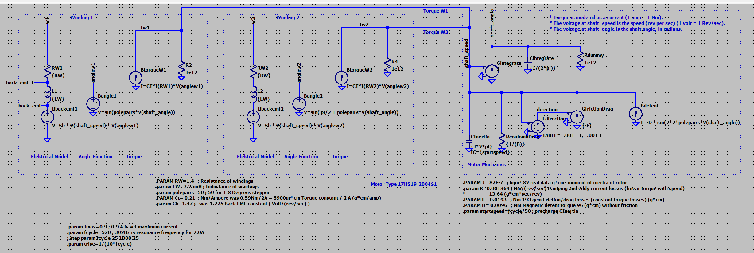
In this model each of the two windings is on the electrical side characterized by a resistance (constant) RW1, a (constant) inductance L1 and the Back-EMF-Voltage. This voltage is generated by the spinning motor.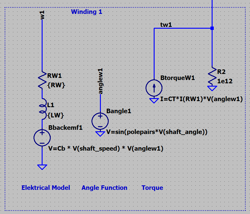
In LTSpice torque is modelt as current 1A=1Nm and speed of the shaft is a voltage 1V= 1rev/sec.
The mechanical side of the winding model is the generation of a torque BtorqueW1.
The torques ( as currents ) come into the part of the model, which deals with motor mechanics: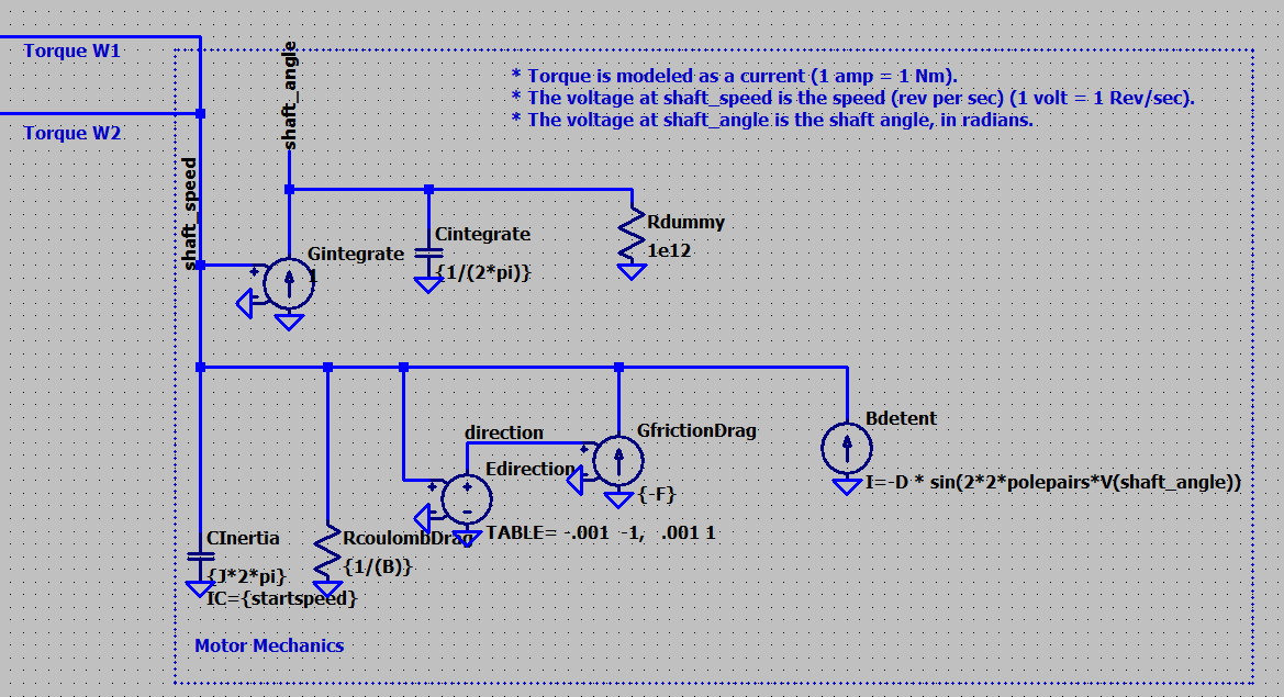
Here we see the inertia as a capacitor a resistor for friction, that is speed dependant, a current source for friction, which is dependant from the direction of speed and the detent torque.
To get the angle of the shaft a current source and a capacitor do the integration.
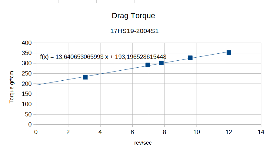
As test-item I decided to use a motor "17HS19-2004S1", which is a Hybrid-Motor Nema17 with length 48mm, 1.8Degrees step angle (50 pole pairs), 0.59Nm holding torque at 2.0Amps, Rotor moment of inertia 82gr*cm², 1.4Ohms resistance and 3.0mH inductance per phase. https://www.omc-stepperonline.com/de/nema-17-bipolar-0-9-grad-44ncm-62-3oz-in-1-68a-2-8v-42x42x47mm-4-draehte-17hm19-1684s
Unfortunately some more data is needed, so I tried to do some simple measurements on my lathe. The setup shall give information about drag torque, detent torque and also about the generated voltage. To measure (average) torques the adhesive tape will lift a weight and the difference will show on the scale below. As the radius is well known, torques can be calculated. To get the speed, the frequency of the Back-EMF-Voltage is documented.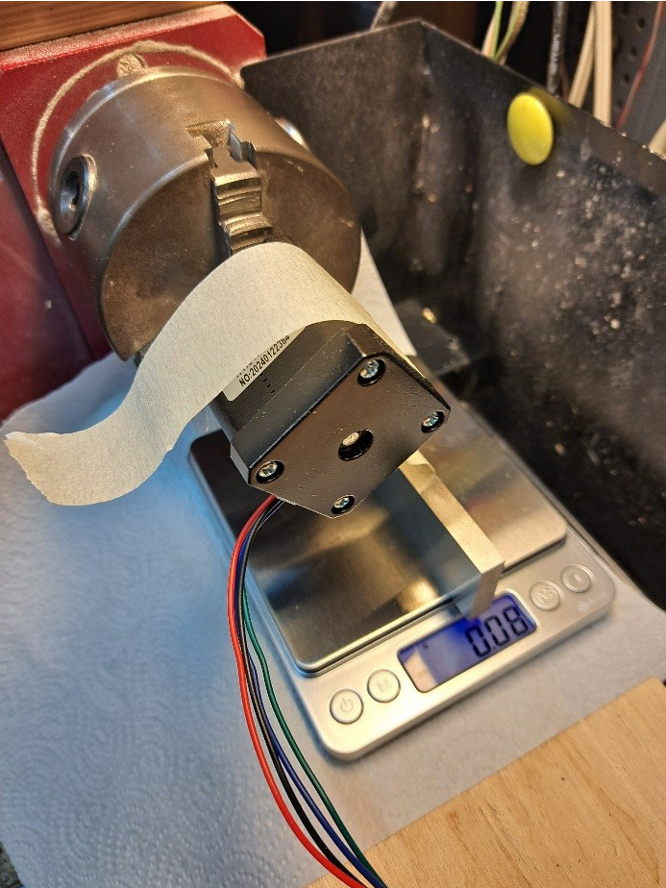
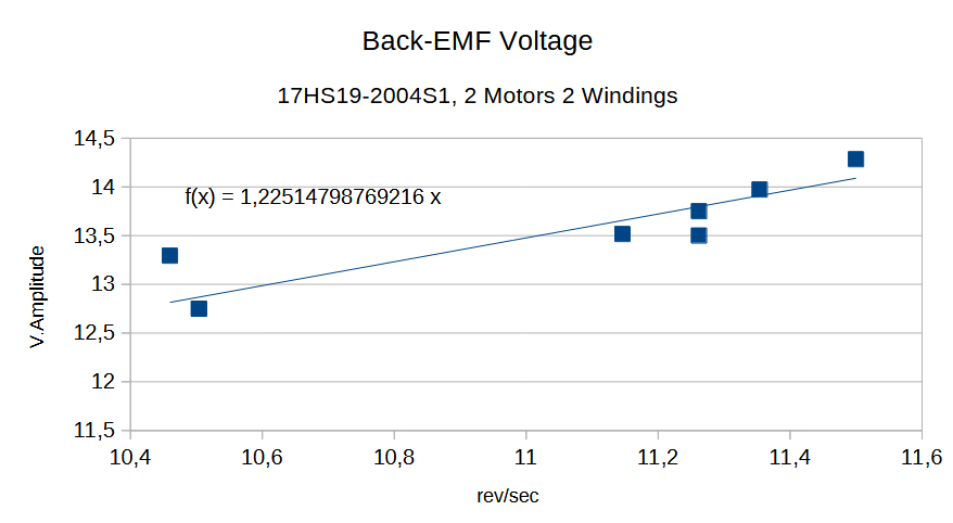
Here I am not sure, about the impact of the simplification of the model. In this measurement only the magnetic field of the permanent magnet is relevant. When the motor is driven by external voltage, the current through the coils will strengthen the field, which should lead to somewhat higher voltage??? ("Reluctance"?) This measurement was used to get the constant Cb=1,23V/(rev/sec)
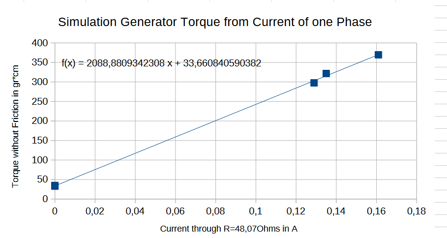
Last not least the motor acting as a generator can be loaded with a resistor. So a current (RMS) will be generated which gives a mean torque. The constant for torque CT from this measurement but multiplied by 2 for both phases is similar to 0,59/2.0A.
Detent torque was "measured" by manually turning the chuck and trying to get the maximum torque. This only gives a rough idea.
The following picture shows the model together with it's parameters for the chosen motor 17HS19-2004S1: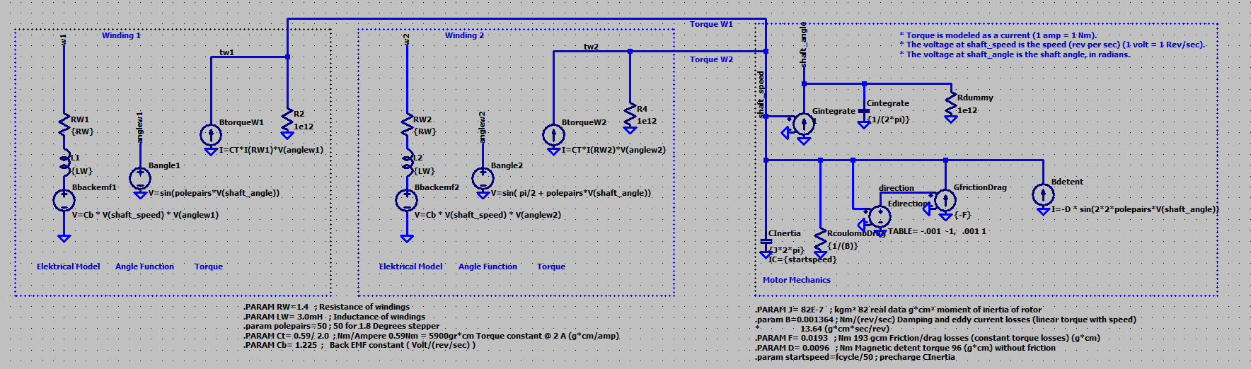
To be continued....
Cheers Christof
Comments
Some update:
To measure T.Hold, a long beam as a lever was attached to the shaft and loaded with a precision weight of 100gr. Moving the weight along the beam while a current of 1A applied to only to one winding brought T.Hold(1A)= 0.21Nm. For 2A it was T.Hold= 0.39Nm.
This is significantly less, than indicated by the datasheet. I wonder, if they applied 2A to each of both windings to achieve 0.59Nm?
Also with my low cost component tester I only got Inductance L=2,25mH instead of 3.0mH.
Measurements at one winding, while the motor ist running.
DRV8825 set to 0.9A, 32 microsteps. Supply voltage 24V. Measurements taken without external mechanical load and after acceleration at constant speed.
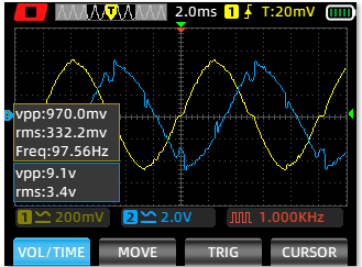
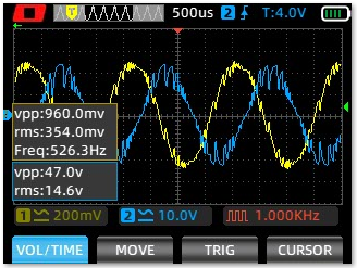
A battery operated Oscilloscope Multimeter was used to measure current and voltage of one winding ground free:
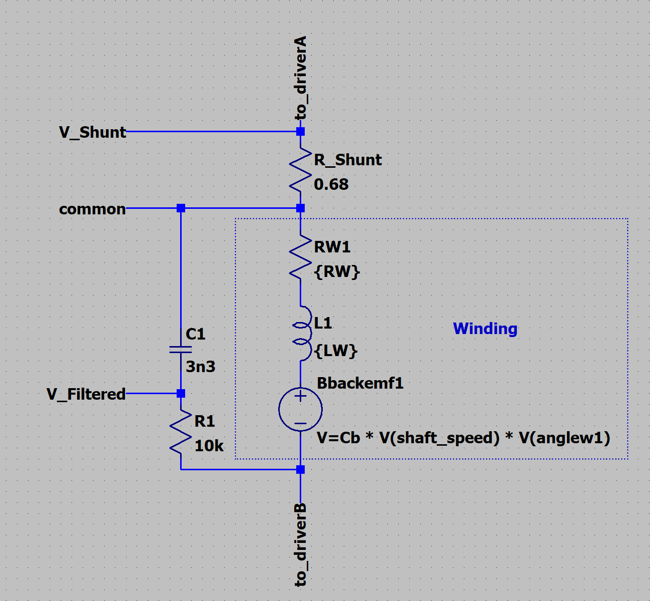
Voltage is filtered. In reality it is digitally driven by a pwm signal. Voltage is negated by the setup in comparison to the current!
Blue ist the filtered voltage, yellow is the voltage at the shunt. At f.cycle= 97.5Hz (4 full steps = 1 cycle) there is plenty of spare voltage, so both signals are sine-like.
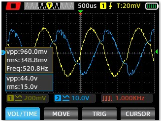
At 520Hz still both signals are sine-like.
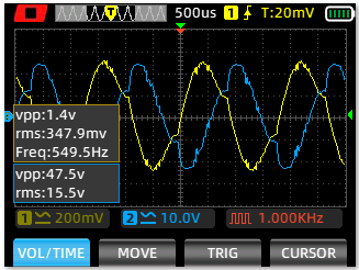
At 550Hz the supply voltage is no longer sufficient to give a full sine. The RMS- Value of the current is still fully given.
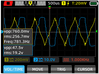
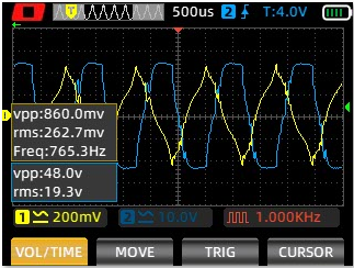
At 781Hz voltage and current have different shapes. I.RMS is reduced.
For comparison some simulation results.
The model was updated with the following data: L=2.25mH. Ct=0.21Nm/A; Cb=1.47V/(rev/sec)
Cb was tuned to get close V.RMS values for the winding voltage in simulation to the measurements at f.cycle=390Hz
Also test points for the back-emf voltage and backemf+Inductance voltage have been added
Simulation with sine-current sources.
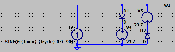
For these simulations for each driver a pure sine a current source was used but it's voltage is limited shunting some current into the DC voltage sources, if too high:
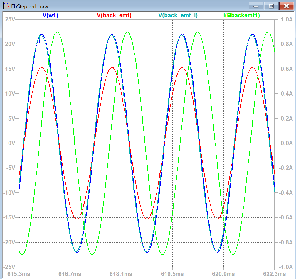
520Hz: voltage and current both are well sine shaped. For me it was interesting to see, that here already some 7volts are spent by the inductance.
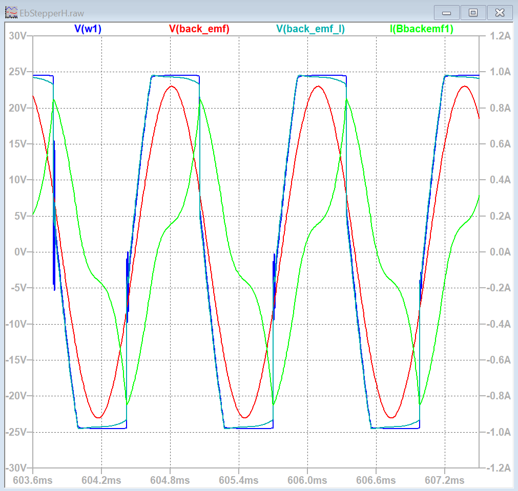
At 781Hz: voltage is cut from a sine. Current goes toward some triangle shape.
So far for today, Christof
Main reasons to dig into this study have been some difficulties with TMC2209 drivers. https://www.analog.com/media/en/technical-documentation/data-sheets/tmc2209_datasheet_rev1.09.pdf
Module: https://global.bttwiki.com/TMC2209.html
I had not been able to get above a certain limit of speed with different motors and with different mechanical loads.
Setup is 32 microsteps, Imax about 0,9A
At f.cycle= 97Hz we can see some difference to the signals with DRV8825: Here the filtered voltage is a very neat sine, while the current is also smooth but less like a sine.
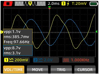
This is generated with the "StealthChop2" voltage control and 256interpolated microsteps.
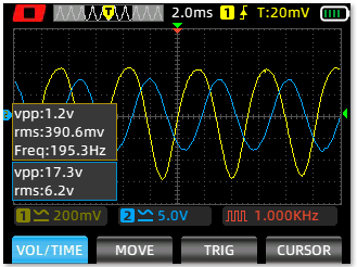
195Hz: Similar nice sine voltage and smooth and even current.
230Hz: But what happens here? Voltage is still a nice sine, but current starts to "dance around".
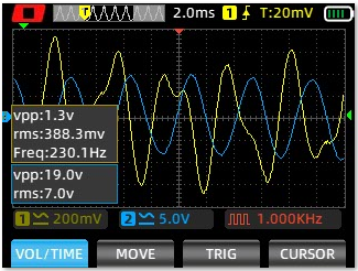
At f.cycle=236Hz the motor stalls. This limit is well away from the point, where the supply voltage is getting insufficient.
#
The TMC2209 module can be switched to from "StealthChop2" mode to "SpreadCycle" mode with a tiny jumper on the lower side of the PCB. So I did this. In this mode current is controlled directly for each microstep.
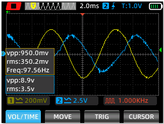
97Hz: Now the current is the nice sine. Voltage distorted.
No more stalling!
520Hz: Vpp is just still under 48V
780Hz: Supply voltage is not enough, so the sine for the drive voltage is cut. Current a triangle now. I.RMS is reduced.
All in all, the behaviour of TMC2209 in "SpreadCycle" mode is similar to DRV8825.
So lesson learned was, that this speed barrier had nothing to do with resonance or "midband instability". It is just, that the TMC2209 has to be switched to "SpreadCycle" mode for f.cycle > 200Hz. Therefore the speed barrier was independent from the motor type or the load driven.
#
The simulation model can be used to study resonance. Here a half-step driver was used instead of sine. f.cycle was varied from 10 to 100Hz in steps of 10Hz.
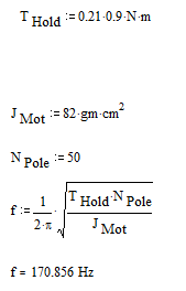
The motor stalls or looses steps at 0.8rev/sec fcycle= 40Hz f.fullstep= 160Hz and also at twice this speed.
A formula about resonance frequency says:
#
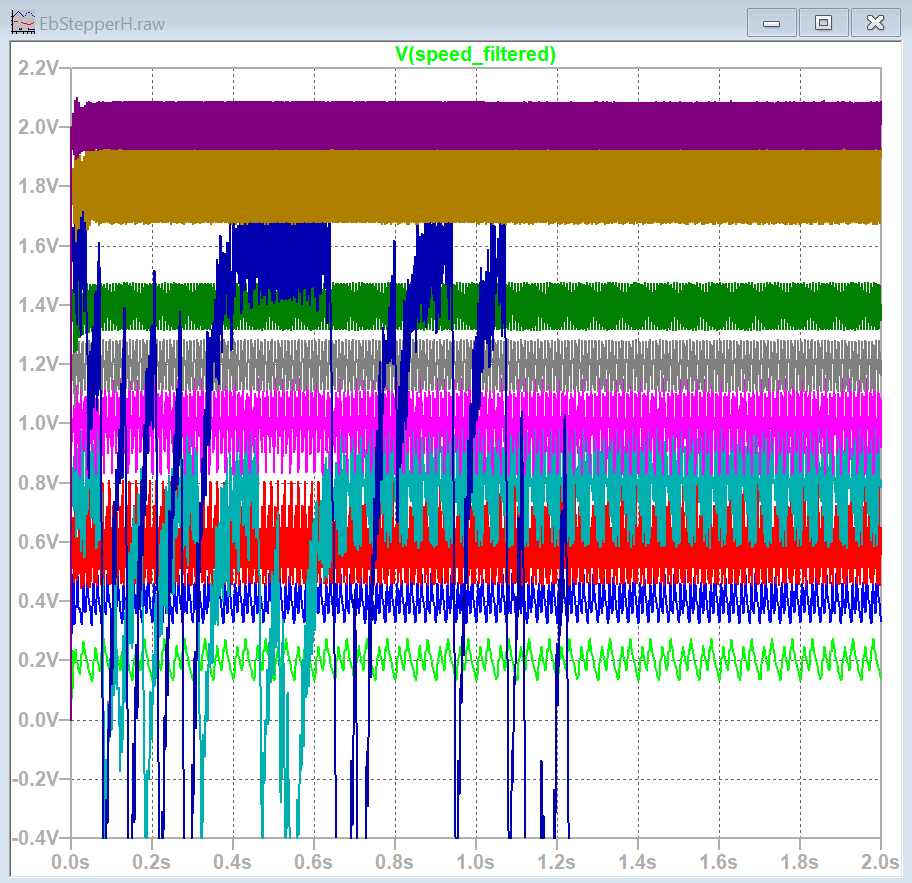
Some idea of the load diagram of the stepper can be calculated with the model too. Here for I.max=2.2A, as the official diagram is given for this torque. Driver is pure sine, but limited to 24V.
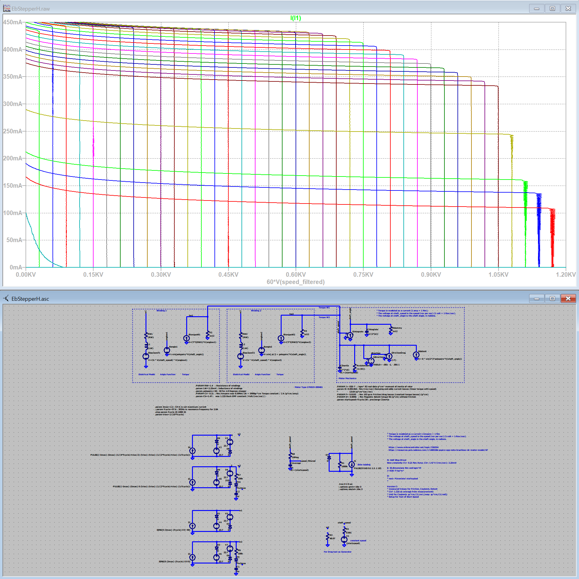
For this diagram the motor is running at different speeds. After 0.1sec a ramp with increasing load torque is applied vertical. When the load gets too high, the speed will break down to the left. Torque 1A=1Nm; Speed in rpm.
I have attached the LTSpice Model.
Cheers Christof