

PCB tricks for ESD protection
 Rayman
Posts: 16,461
Rayman
Posts: 16,461
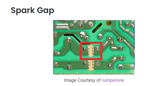
In a recent Parallax Online Forum, Chip Gracey showed a PCB spark gap, which was very interesting.
Never seen this before and am very interested... There can be some extreme events in my line of work with high voltage...
It was like the bottom one here:
https://atadiat.com/en/e-four-pcb-marks-part-2/
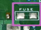
Another very interesting thing is the PCB fuse shown in the above link.
Think want to add both of these to next PLC type board where inputs come from wires to the outside (of cabinet) world...
Don't think the fuse is very controversial, although have never seen it used. Seems like a good idea though...
Seems there is some debate over the spark gap though. Guess the main thing is limited lifetime. So, this brings up the goal of using this and it is going to depend heavily on the particulars of the application...
Comments
Yeah, I've seen both those before. Cheap AC-DC power supplies tend to have both. The fuse trick is for when the regulator blows up - making it a throw away.
Spark gaps built like that aren't going to work on lightning strikes. You're designing for dealing with static discharges from clothing or maybe off the machinery. When the air gets dry, static becomes a real hassle.
Something like a lightening strike on a wire connected to a controller seems like could be very complicated...
First, the wires are coming in on a shielded cable, so seems like a very large voltage would just arc through the ~600 V rated wire insulation and connect to ground.
So maybe how much voltage can actually get the PCB is going to be limited...
There is also a temporal component. Maybe a very short HV pulse could make it through before the insulation collapsed.
Anyway, what comes after these PCB things is probably going to have some kind of TVS or optoisolation as well, so doesn't have to do all the work...
Will think some more about this in terms of my particular goal of keeping the controller alive and talking, even if all the I/O is broke...
@evanh Guess the fuse doesn't really make sense for ESD... Does sound like something more for power supplies, as you said.
Having this on the 5V input from USB might make sense though. Or maybe not, have to think about it...
Come on, those tricks are for dirt cheap power supplies, not for any serious equipment. The problem with the fuse trace is that it needs a much higher current to blow as would be good for the reliability of the board. The solder stop paint becomes brown and begins to smell funny at 2-3A for a 0.5mm trace. But it requires >30A to really blow. The voltage at which a spark gap begins to fire is heavily dependant on air humidity and dust contamination. When clean and dry a 1mm gap can take multiple kV without a spark. Wet and dirty it breaks down at a few 100V. And once it has fired carbon from burnt dust can accumulate degrading the breakdown voltage further. Even small tolerances from the etching process can have a large impact on the breakdown voltage. It matters if the copper edges are sharp or dull.
So please use real fuses for overcurrent and real varistors or TVS diodes for overvoltage protection. They cost only 5 to 10cent. Not worth risking failures. And if they blow up they can be replaced.
@ManAtWork I might be with you on this... Also thinking that TVS is going to be faster than air arc, so would go first...
It's also strange that very few people mention these spark gaps and no actual companies seem to mention it at all (well, that might be because it's free).
Still, seems like if it were a really good idea, there would be a lot more on the internet about it...
Also, cannot find an Eagle footprint for this anywhere online...
Message deleted
Just occurred to me that the little device we use to protect USB from ESD should also be great for just general P2 I/O pins.
It's overkill because don't need 5V switch, but saves on BOM lines...
https://www.digikey.com/en/products/detail/texas-instruments/TPD3S014DBVR/5138394
Actually this might be perfect for feeding four P2 I/O and 5V to RJ45 connectors for general purpose PLC usage.
Need two of them, but that would protect the 5V as well. The ones I have limit current to 500 mA, but two of them should allow up to 1 A or so (if they share nicely).
That seems like should be enough for most things...
Series resistor with small capacitor bypass works for most human-body cases. I use a series resistor as a fuse with a zener bypass if I think something really nasty might happen. (24V to logic short..) or several resistors to build enough gap with capacitor and zener, maybe even a GDT if I think something 300 volt-ish or more might happen, but at that point it's more about avoiding fire than any kind of fault tolerance.
Think I'm liking these TVS arrays: https://www.digikey.com/en/products/detail/texas-instruments/TPD4E02B04QDQARQ1/7732454
It can just sit on top of four P2 I/O pin traces (as in the four that go to an RJ45 jack for external connection).
And, you have the choice of populating or not populating...
They are really good. Here is something very similar that does 8 pins. These packages get SOOO small. The 100 ohm resistors take a LOT of the edge off of high Dv/Dt stuff and _probably _would open up for something sustained.