

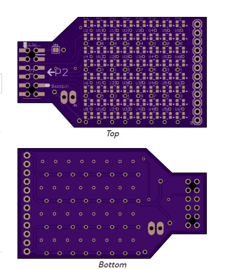
RGB LED Array accessory for Eval type header
 Rayman
Posts: 16,445
Rayman
Posts: 16,445
Found these lower current version of WS2812 RGB LEDs in 2020 size:
https://www.smart-prototyping.com/WS2812-2020-Addressable-Fullcolor-RGB-LED?search=WS2812-2020
Seems some places are calling the low current version WS2812C.
WS2812C is 5 mA per led whereas WS2812B is 12 mA per led.
This is still a ton of current for an 8x8 array if all turned on.
It would likely exceed the 500 mA limit from the regular single USB to FT231X 5V power.
However, seems most board have a second USB source for power or one main high current supply. This should probably be enough.
Or, could dial down max brightness to 33% on all LEDs and that should be good.
Still, added a couple places to provide extra 5V power on the board...
Just ordered via OSHPARK. Can't do China right now due to lunar new year...
OSHPARK was actually very reasonable cost and time to get some prototypes...

Comments
Cool. I did one of those, too. I have the boards and the parts, I've just been too busy to populate and pop into the toaster over. Josh and I use a couple of 8x8 WS2812b arrays in one of our products and I thought this would give us something to use for experimenting with animation "cells." Again, not finished yet because it's a "nice to have" not a "must have" at the moment.
Your board has more features than mine; I stuck to one pin and the pixels are powered from the 5v pin on the accessory header so I know I have to manage current. I wouldn't have considered trying the 2020 pixels in the past, but my friend Rick used them in the robot called "4" in the last Superman movie, so I decided to give it a try.
Great find! WS2812C’s lower current helps, but power budgeting still matters. Extra 5V inputs and brightness limiting are smart choices. OSHPARK is a solid call for quick prototypes.
@Rayman Since I know you have the hardware, I bet my Blitzen24 firmware will drive that board quite nicely")
I am working on a similar project, though I am looking for a wireless solution, probably an ESP32 to drive it. It is a singling bulb Christmas ornament that can do lip-syncing with Xlights and Vixen.
I may reach out and PM you about your OSHPARK experience.
Your animated LED ornament looks great, good luck with it!
@ke4pjw OSHPARK worked out well. Picked the fast service and boards came in 8 days. Wish they were blue and wish Qty. was 4, but speed and price is perfect.
Also found today that they will accept a board that is several boards in one with breakaway tabs. Nice that they allow that...
Also, LEDs came in tape. This is excellent. Means can use pick and place one day when get stencil...
@JonnyMac Looking at your driver (OB2857)... Thinking ADDPINS 7 might get all 8 rows to show the demo. That would be very nice...
I'll do you one better: a driver with 8 (contiguous) outputs that can all be independent. A couple of years ago Terry Trapp needed a multi-channel pixel driver so he and I both created versions. Mine is attached. This will give you more flexibility than writing the same data to every pin.
The screenshot shows four channels so you can see that there is different data on every output.
Edit: Corrected driver in post #25
"Addpins 7" works! Turns single string demo into 8x8 demo...
https://www.youtube.com/shorts/AZ2Rf481aro
Will try the new 8x8 driver by @JonnyMac next...
Really happy with light level and current use, must be <500mA as just powered by single USB cable...
This was what was hoping for.
Don't think demo does all LEDS on full power though, might test that...
Or, maybe not, that would be close to 1 A in theory...
Cool. Looking forward to seeing if the 8-channel driver works for you. I tested with a few LED rings and looked at signals on a logic analyzer, but it will be nice to see it on your board.
@JonnyMac Do your drivers include some kind of overriding limit on max brightness?
I'd like something like that set at 30% or so to start with, to make it less likely to overload USB power...
Use this method to set you RGB color to a specific level.
pub scale_rgb(rgb, level) : result

'' Scales rgb ($RR_GG_BB_00) value to level
'' -- level is brightness, 0..255 (0..100%)

  org
                        cmps      level, #0             wcz     ' 0 or lower?
        if_be           jmp       #.done                        '  yes, return 0

                        mov       result, rgb                   ' get input color

                        cmps      level, #255           wcz     ' 255 or higher?
        if_ae           jmp       #.done                        '  yes, return input

                        movbyts   level, #%%0000                ' make multiplier
                        mulpix    result, level                 ' scale the color
.done
  end
There is nothing in the driver code that limits what is sent; this is the responsibility of the code that fills the buffer(s).
Removed by JM until driver fixed.
Corrected driver in post #25
Will do.
Think need to make some current measurements to see what real world draw is…
Remember now that the @JonnyMac strip demo has brightness set to relatively low values, $20 out of $FF (32 of 255).
Setting to $FF makes it super bright and also draws a lot more current.
Making some notes here on current draw:
Red Only $FF = 318 mA
Green Only $FF = 302 mA
Blue Only $FF = 277 mA
This gives me a chance to test out the second USB-C connector on the P2 Platform board, meant for power only.
There is an issue there though... There's a Zener diode in series there, meant to be a backstop. But, it drops 0.55 V at full current, which is enough to mess this up.
So, put a jumper over the Zener.
Red + Blue $FF = 702 mA (multimeter switched from mA to 10 A setting)
Red + Blue + Green $FF = 1026 mA It's bright! Hard to look at! Board is getting a bit hot too...
Guess this is close to rated value: 8x8x3x5 mA = 960 mA.
Probably within multimeter error range...
Array draws 45 mA even when all off. Interesting. Have to see if datasheet supports that...
Took a minute to record current (using multimeter on 10A setting) vs level for all three colors.
The current vs color is almost perfectly equal. So, each color draws same current for same setting.
The current seems to match the datasheet: with max of 5 mA per color per chip, or 15 mA per chip, 120 mA per row, 960 mA for whole array full on.
If just using regular USB for power, probably want to limit max level to some value due to 500 mA total current limit.
Guess the $20 setting in the @JonnyMac driver is good. $22 draws 74 mA per color --> 222 mA total if chips and colors set to $22.
@JonnyMac Your 8X driver codes above don't seem to work, not sure why not yet...
I don't have 8 strips, but I did take an 8-pixel strip and connect it to each of the IO pins defined in the code and I am getting slowly scrolling colors. Did you adjust the pins for your program? An important point is that the driver (at the moment) expects the app to use eight contiguous pins that are in ascending order. In my demo I'm using pin 32..39.
Adjusted to P16 base... It does clear the array, so is writing to it... Guess need to test with Eval board, so can put on base P32....
Set pins back to base 32 and ran jumper from P32 to P23 and that looks good...
Set back to base 16 and am seeing data on the pins using scope. But, looks like just sending 0's...
Darn, I see that, too -- and I was sure I tested in both output groups (outa and outb). Will investigate and fix. Sorry for the trouble
Update: Works with base at P0 or P32. Will sort out why it won't work offset from start of group.
Corrected driver in post #25
Does look good on Eval with basepin 32...
It's funny how sometimes asking for help -- even without getting it -- triggers something in our own brains. I sent Chip a text this morning asking if I could chat with him about the driver. He replied that we could chat this afternoon. Great -- that works. 30 seconds later I had and idea, and that idea was the solution to the problem I was having with the driver (misalignment of the parallel output bits). I also looked at the latest version of the Spin interpreter and noticed that Chip made a subtle change in pinwwrite() so I followed that change in my code.
Anyway, this version seems to work; I tested it on P16 and other pins, too, just to make sure that it will work anywhere in the group (outa or outb).
Please give this a try, @Rayman, and let me know how it works for you. It's already set for P16 so you should be able to unzip it and go with your new PCB. Thanks.
It works! Looks great too... Thanks.
@JonnyMac Found your old inline assembly driver and am playing around with it... Works with addpins 7 too...
Thought there was a new one, but couldn't find it...
Excellent!!! Thanks for giving it a try.
If you use addpins() you'll get the signal from every pin. The point of the driver attached above is that it allows each pin (up to 8) to have its own signal set. In fact, internally it does the equivalent of addpins() to turn the base pin and the number of pins in the group (up to 8) into a P2 pin group. The drvh and drvl instructions work with pins or pin groups, but if you want to have different bit states in the group you have to use muxq with the group (again, this taken from the Spin interpreter pinwrite() code).
This makes a mask for the defined pin group
                        mov       t1, outscount                 ' make mask for outputs
                        sub       t1, #1
                        bmask     outsmask, t1
                        shl       outsmask, outs
This turns the base + count into a pin group (t1 starts with count-1 from above)
                        shl       t1, #6                        ' convert outs to pingroup
                        or        outs, t1
This code is the equivalent of pinwrite() after the signals from each stream have been moved into a parallel group.
wr_outs                 testb     outs, #5              wc      ' lsb pin in outa or outb?
        if_nc           setq      outsmask                      ' mux pixouts into outa using outsmask
        if_nc           muxq      outa, pixouts
        if_c            setq      outsmask                      ' mux pixouts into outb using outsmask
        if_c            muxq      outb, pixouts
If doing the same thing on each of your pins fits the application, I've attached my latest no-cog WS2812b driver. I wrote it for a work product because we only have 45 LEDs and they're not updated frequently -- didn't seem like a good idea to spend a cog, and with inline PASM we don't have to. The setup for this simple:
...so you could easily switch between the pins on your pixel board if you're not doing high-speed animation.
Need to do the math to see if using 8 pins for the array is crazy overkill or not for animation…
There are times when multiple independent outputs are needed, as in Terry's light show products which inspired me to write that 8x driver. We have another new product that uses two 8x8 matrix displays, but those are on a single pin so we can write to one 64-long buffer to update the display. We do a simple X/Y arrangement of pixels so I can write simple plot and line functions as I would for an OLED or other pixel-based display.
You can do 40fps with up to about 900 pixels in series on a single pin. Power requirements are always the difficult part. With most of the "bullet" style pixels, I typically "power inject" every 200 pixels. For seed pixels, I inject every 400 pixels. 40fps is my target framerate.