

Inductive proximity sensor--how does it work?
 mpark
Posts: 1,336
mpark
Posts: 1,336
I have this device: QS18-05N-1 Proximity Switch.
I use it to detect the presence/absence of a steel ball, as shown at 53s in this video. Note that the ball is not magnetized.
I have two questions:
1. How does it work? I'd love someone to explain like I'm 5.
2. Does anyone know of a similar device that's shorter (in the vertical direction when oriented as in the video)?
I'm primarily interested in question 2 but I figure I should also try to learn something!
Comments
There's a link to the datasheet right on the sales page. In that datasheet you'll find a circuit diagram -- I clipped and edited.
That device is NPN/Open-Collector. What this means is that pin 4 (black wire) is either floating (like an open switch) or connected to ground. If you want to monitor that with a microcontroller like the Propeller, connect a pull-up (e.g., 10kl) to pin 4 and the other side to 3.3v. When the sensor is idle, the Propeller input pin will see a high; when the sensor is active, that pin will go low. Easy peasy. Note that the sensor is powered by 12v, and the ground on the sensor and the microcontroller must be connected together for this to work.
https://www.balluff.com/en-us/blog/the-basic-operating-principle-of-an-inductive-proximity-sensor
https://www.baumer.com/int/en/service-support/function-principle/working-principle-and-technology-of-inductive-sensors/a/Know-how_Function_Inductive-sensors
"... creating an alternating electromagnetic field that emerges from the active surface of the sensor. Any metal object approaching the front will induce eddy currents draining energy from the oscillator."
As for size and shape, it looks like you've got it sitting sweet as is. I wouldn't change what you've got.
Here's a Q&A along the lines of Jon's answer - https://www.ifm.com/gb/en/gb/landing-page-uk/proximity-sensors-explained-types-applications-and-benefits
Thanks, I did manage to wire it up. I was actually hoping for more insight into the mysterious "Proximity Sensor main circuits" box
Ah, that is the sort of information I was hoping for. Thank you!
Well, I would much prefer something that takes up less vertical space, so if anyone has any leads, LMK!
How about this one?
https://dfrobot.com/product-2025.html
Sensing distance is 4mm (I think the one you use has 5mm), but it's quite small.
Andy
smallest, cheapest with 4 MM sense distance in my goto parts list is https://www.automationdirect.com/adc/shopping/catalog/sensors_-z-_encoders/inductive_proximity_sensors/small_rectangular/aps4-12m-z-d
I'm guessing there's an RF coil inside and it monitors for a change in the resonant frequence of the LC circuit...
I'm imagining it's like those old AM radio kits where you move a ferrous part in and out of a coil to change frequency...
Whoa, Andy, that's perfect! Since I want the detector to be underneath the "detectee", this will take up only 6mm of vertical space.
Assuming, that is, that the little crosshair symbol indicates the detection area.
That's the front-sensing version; I'd go for the top-sensing version so it would be 12mm "tall" in my application; a good second option.
Thanks everyone!
Sounds like you found a solution, but I remembered a PE kit article from Parallax which had a metal detector, check out ~page 180,
https://media.digikey.com/pdf/Data%20Sheets/Parallax%20PDFs/Propeller_Education_Kit_Labs.pdf
Very interesting--thanks for that!
just an observation. It looks like your prox arrangement is working just fine in the video. Maybe more accuracy isn't needed, but from a microcontroller standpoint inductive proxes are very slow and tend to have a granularity at their oscillator frequency, (Usually 4 KHZ).
If you find more precision is needed, you could go for a 'guitar pickup' strategy with a very small magnet and coil or hall-effect sensor. Even non ferrous balls will pick up an eddy current as they pass and 'blip' the coil or sensor. Anything that will work with an inductive prox will work that way. Then the granularity is in your microcontroller, and propeller 1 or 2 is pretty fast...
Hi, this is interesting!
Do you have an example of such setup with schematics? I ask, because a Guitar pickup has a very high number of windings and still has only about 50mV amplitude? Movement of the string perhaps 2mm at 4mm distance to the pickup. Some sort of amplifier would be needed?
@"R Baggett", I too would love more details! Not that I need more precision for my application... or maybe I do and I just don't realize how much better things could be.
I'll work up a schematic and do some experimenting so I can present something that will work in this circumstance. In the guitar, there is a very light target (String) that is relatively far from the coil/magnet. The mass of the ball here will intercept a lot more lines of force, and therefore a larger 'blip'.
In practicality, it may need some amplification , or to be biased near the threshold of an input pin.
Apologies, As I search my small workshop, I do not find a suitable magnet, enough magnet wire, or targets. This will need to wait until I return to work Tomorrow.
Early results, with a monstrous, but very unfocused horseshoe magnet and about 50 turns of wire while waving an aluminum extrusion at the assembly, and observing the output of the coil on an oscilloscope has encouraged me, and convinced my Grandson that I've lost it...
Experiments at lunch:
2 magnets on a coil salvaged from a 24V DC relay. The magnets are 1/4 " diameter and apx 17/32" long. Unknown composition, but not impressive magnets at all.
The oscilloscope capture is from sliding my wire stripper across the plastic jaws of the vice. Non-ferrous experiments with these weak magnets were disappointing. Better magnet(s) and pole pieces should help a lot.
I will work on a one-transistor amplifier for this, it won't take much to go from 250mV p-p to clip negative at 3V3 resting.
I attribute the 'ring' at ~ 130mS to vibration from the wire strippers going over the edge of the jaws.
Very cool!
@"R Baggett" said:
OK, seeing your experiments I went back to your earlier comment and thought I'd try my own experiment with a Hall-effect sensor. I saw that Parallax sells one and I was about to place an order, but I looked through my order history and realized I had actually ordered a couple of them a few years ago! I never did anything with them then, but I guess my past self knew something. Kind of a miracle. Even more miraculous: I was able to find them.
So I hooked one up and put a little neodymium magnet behind it, and now I can wave a steel ball in front of the sensor and an LED turns on! Who knew it could be so simple?!
Thanks for the nudge in the right direction!
Not abandoning this, Had a busy weekend and just received small, but mighty neo magnets.
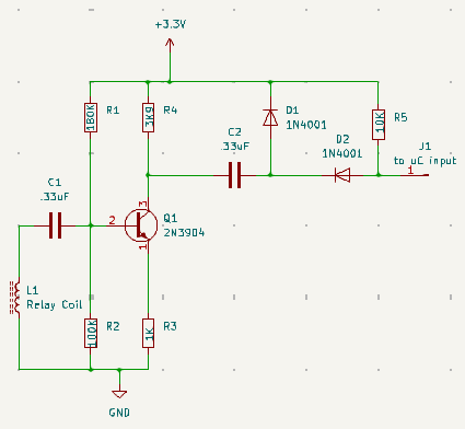
This amplifier should have a V gain of about 10 dB, will certainly clip for the signal shown. D1 and D2 to ensure full negative drive. Will add 100 ohm resistor before uC input to soften any possible negative overdrive.
again, THIS IS NOT TRIED YET.
I am doing this because it is interesting. It is possible that the interference to the ball caused by the magnets involved will overcome any advantage of accuracy in the OP use, but not for me to decide.
Interesting thread! For another option, that happens to be about the same price as the DFRobot sensor but significantly smaller, is a Magnasphere L Series Magnetic Switch. These are about 1/4" tall and less than a 1/4" in diameter. Essentially, there is a small magnetic ball inside that is sitting in a manner that both leads are connected (normally closed) and when a ferrous metal is within its "sensing range", the magnetic ball is more attracted to it and it is lifted off the contacts making an open. They are quite fast and should work with the steel balls in this scenario. No electronics are required, but it would produce a very short pulse, so debouncing/conditioning might increase reliability. You get the advantages of a reed switch, but no magnet required.
https://magnasphere.com/products/switches/l-series/
These are the ones that I have used personally: https://www.digikey.com/en/products/detail/magnasphere-corp/MG-B2-6-5-L/1680359
I can send you one if you want to try it.
That's a simple solution. I am hoping mine will work with non-ferrous also. I have the circuit breadboarded, sitting there in a box mocking me, but I have been way busy at work and home. Maybe tonight!
Non-ferrous may require capacitor bypass on R3, but that might just be too much and peg for noise and /or become an oscillator...