

Spi-ish question
 R Baggett
Posts: 272
R Baggett
Posts: 272
So, I just tried to use jm_ez_spi to operate a TPIC6595 (Shift register with open drain high voltage/current outputs.
I tried slowing things way down (1 khz) and still had some strange going on.
So here is what happens:
In the attached archive I have 'Hardware_00' with 3 possible tests that can be selected in 'Setup()'
Test1 After fiddling around, and then turning ALL outputs on and off, this works. see Test.png where yellow is clock, cyan is data. magenta, is output latch load, green is output. it works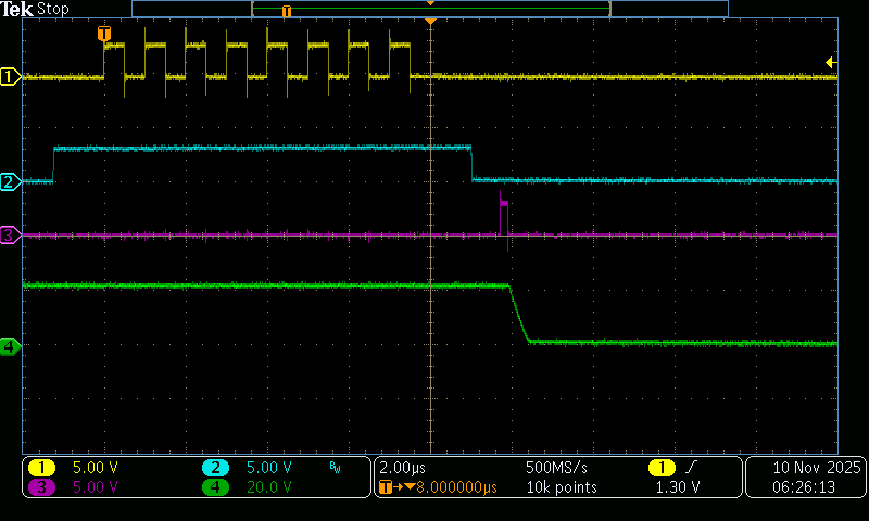
Test3 is with the outputs alternated. it does not work. It is my understanding that spi clocks data in on the falling edge of the clock, and the waveform looks perfect for this interpretation. It just doesn't work..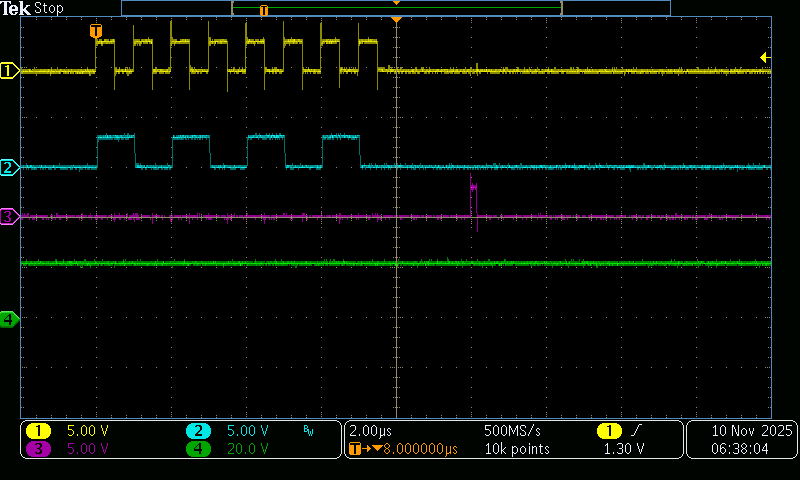
From this I surmised that the chip wants to clock on the leading edge of the clock, so I built Test 2, which works just fine, but ignores the special capabilities of the P2.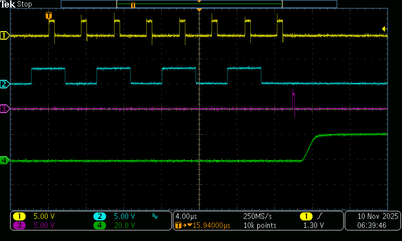
so, my question is:
Can the SPI mode be adjusted to land the clock in the middle of the data? or switch edges?

Comments
Hmm... There is a polarity inversion flag in the smartpins. Maybe that would fix it?
I figured out how to do the inversion, (perhaps not the only possibility, is there a better one??). It shifts the change of the next bit of the dat to about 38 nS after the positive clock, i think the chip doesn't like that... it's just not that fast.

Here is what I tried in jm_ez_spi:
Perhaps I have misapplied ez_spi here, since this isn't really spi...
Thanks!
You might try inverting the clock pin to switch edges. I do that in my flash at the suggestion of others to create fewer issues with the onboard SD card (which I don't use).
It does.
The object you cite is very old, and I don't think I ever deployed it in any of my own projects (except that flash driver).
Given the speed of the P2, you could go straight Spin. I run at 200MHz and this Spin code will output at about 600kHz
con

  MOSI = 32
  SCLK = 33

  #0, LSBFIRST, MSBFIRST


pub shiftout(mode, value, bits)

  if (mode == MSBFIRST)
    value rev= (bits-1)

  repeat bits
    pinwrite(MOSI, value & 1)
    pinhigh(SCLK)
    pinlow(SCLK)
    value >>= 1

  pinlow(MOSI)
Of course, it will slow down a bit if you want to use variable pin numbers. Here's the output of $CF in MSBFIRST mode
If you have the need for speed, you can use inline assembly. Honestly, this is what I do most of the time for SPI devices. Bit-banging is assembly is often less code than dealing with smart pins.
con

  HCTIX = ((CLK_FREQ / 5_000_000) >> 1) - 10

  MOSI = 32
  SCLK = 33

  #0, LSBFIRST, MSBFIRST


pub fast_shiftout(mode, value, bits)

  org
                        testb     mode, #0              wc
        if_c            rev       value
        if_c            rol       value, bits

.loop                   testb     value, #0             wc
                        drvc      #MOSI
                        waitx     ##HCTIX
                        drvh      #SCLK
                        waitx     ##HCTIX
                        drvl      #SCLK
                        shr       value, #1
                        djnz      bits, #.loop

                        drvl      #MOSI
  end
It's a little trickier using variable pins with inline code -- though you could pass your MOSI and SCLK pins as parameters. If they're constants you can see it's no trouble. The half-cycle clock timing is tuned to get closer to the target of 5MHz.
Jon,
I think you are absolutely right. My Test2 data above was originally almost exactly like your Spin example above... it was too fast for the TPIC6595 and I had to add delays to get it to work!
That solution is perfectly adequate, and is as you said much shorter than the smartpin version. Just not as cool... and I am still done with all 8 bits in < 12 uS (Using FlexProp).
Thanks!
If you need precision, I'm sure there's a way to do inline PASM in FlexProp -- I just don't know how. Good luck with your project.