

Platform3 (Concept)
 Rayman
Posts: 15,612
Rayman
Posts: 15,612
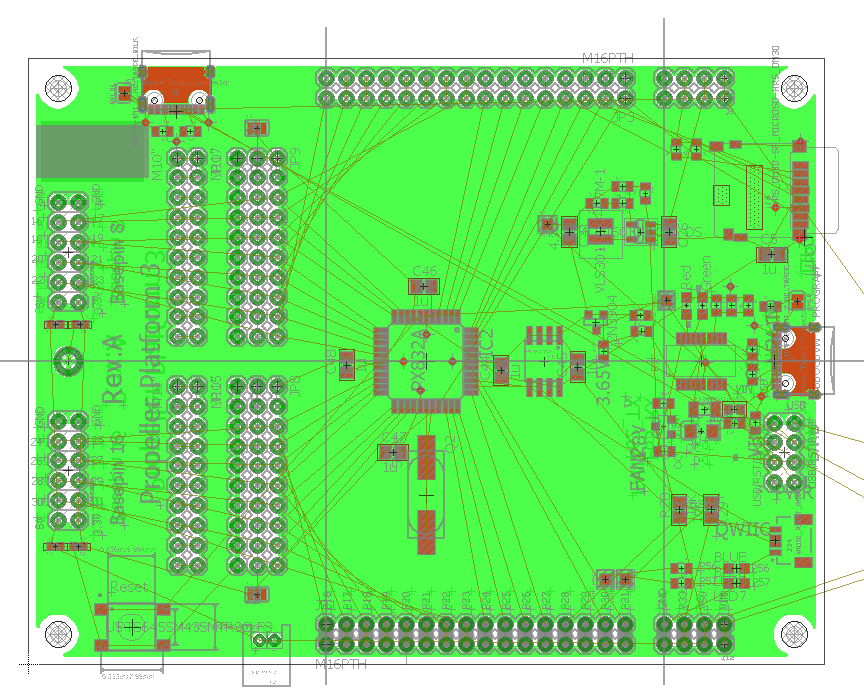
Need a new P1 board for a battery powered full color E-Ink display...
Haven't made a P1 board in a very long time, so this is fun.
Here's the concept so far (see image).
Think the last "platform" board for P1 that we made was called "Express".
This is an expanded update.
USB connectors updated to USB-C
FTDI chip updated to FT231X.
Doing this in Eagle, think was ExpressPCB last time. That was smaller, this is full size...
Adding a QWIIC connector (cause that's an easy way to add peripherals).
Added two P2 style headers, not sure what will do with those yet.
Adding a middle proto area. This is where the E-Ink adapter will connect.
Could have two of them...
Adding a second USB-C connector for power only (no serial).
Adding two pull-up resistors to uSD, even though maybe not 100% needed.
Adding a couple blue LEDs.
Think that's about it...
Comments
If you have µSD, you can probably add a spot for a 23LC1024 RAM chip (sharing the same SPI pins). They're pretty neat for low-complexity volatile storage (P1 being of course super RAM starved at all times)
Neat board, Ray.
Do you have a power pin (PFET) to cycle power on the uSD?
Is the Qwiic port shared with the EE I2C pins? One thing to be mindful of is that the P1 drives the clock line and the boot-up I2C frequency is a little over 250kHz. Devices that can only tolerate 100kHz (usually devices with small processors) can interfere with writing to the EE. I had this happen with a Sparkfun I2C 7-segment display and had to move it to its own set of pins.
@Wuerfel_21 Maybe just use the same APS6404L PSRAM chip as P2 Platform and other P2 things? Seems to have an SPI mode...
@JonnyMac Is there any P1 board with power pin for uSD? Could add one with option to bypass if need the pin.
You might be right about I2C pins. Do not want anything messing with boot from EEPROM. Can add solder jumpers to disable the pullups. Actually, think most QWIIC things come with pullups. Is that true? Think so...
That is a good question (and would be a boon as far as capacity goes), but those have the problem that they have a max. CE low time of 4µs (vs no limit on SRAM). This is not a lot if we consider SPI mode + slow P1 clocking (enough for a few bytes at a time only). Though IDK if the same limit applies to the slow 33MHz read command (P1 limit is 20MHz). Also, it's apparently not possible to reset the part into SPI mode if it got into quad mode and SIO2/SIO3 are not connected (consider the command table).
The 23LC1024 I know works well and can be read/written from Spin even.
The parts both have the same pinout though, so can easily try it both ways.
@Wuerfel_21 ok thanks. Same pinout makes it easy…
Unrelated off-topic oddity: The AP datasheet claims max. higher clock speeds for 3.0V vs 3.3V -> might make sense (on P2 boards) to regulate that whole VIO bank down to 3.0V
I created a P2-type accessory that works with the P1 and the P2. Having power control requires an extra pin, but given the tricky nature of uSD cards, might be worth it.
I think you're right. You might put light pull-ups (e.g., 47K) on the EEPROM so that if nothing is plugged into the Qwiic port (assuming it's shared), things don't get too stiff (though that's usually not a problem in my experience).
Don't need power switch if you're just going with SPI mode, don't think I ever saw a lock-up even under extreme access patterns. It is needed for native SD mode, since if you enter it once, you can never ever get back out of SPI mode without a hard reset, but we're not doing that on P1. Also the pull-ups for the SD data pins need to be behind the power switch for it to work 100% properly, which would be annoying for secondary use of the SPI bus.