

BLDC Super Bundle Put Together
 iseries
Posts: 1,547
iseries
Posts: 1,547
I thought I would get this bundle because it was inexpensive, and I needed a winter project to keep me busy.
Since I only program in C and I don't use SPIN I knew I was going to have to write everything from scratch. Not a big issue.
The first thing was deciding on a piece of wood to use for this project. I don't have a circular saw to make the rounded board shown in the video and looked for a simpler piece of wood to use. I got a 3/4 inch 2x2 finished on one side piece of wood from the hardware store for about $10. I then cut it in half to use as my board.
One of the problems was that the Edge breakout board uses smaller holes then does the P2 or the BLDC board so mounting it to the wood was going to be an issue. I normally use 3 mm screws in all my projects so it would have been nice if that was the standard size holes on all the boards.
Next the serial adapter was a very tight fit with the BLDC board plugged in at the same time. Also, with two boards plugged in there is no addition ports to add sensors to the project. I guess I will have to purchase the new Edge breakout board with more headers.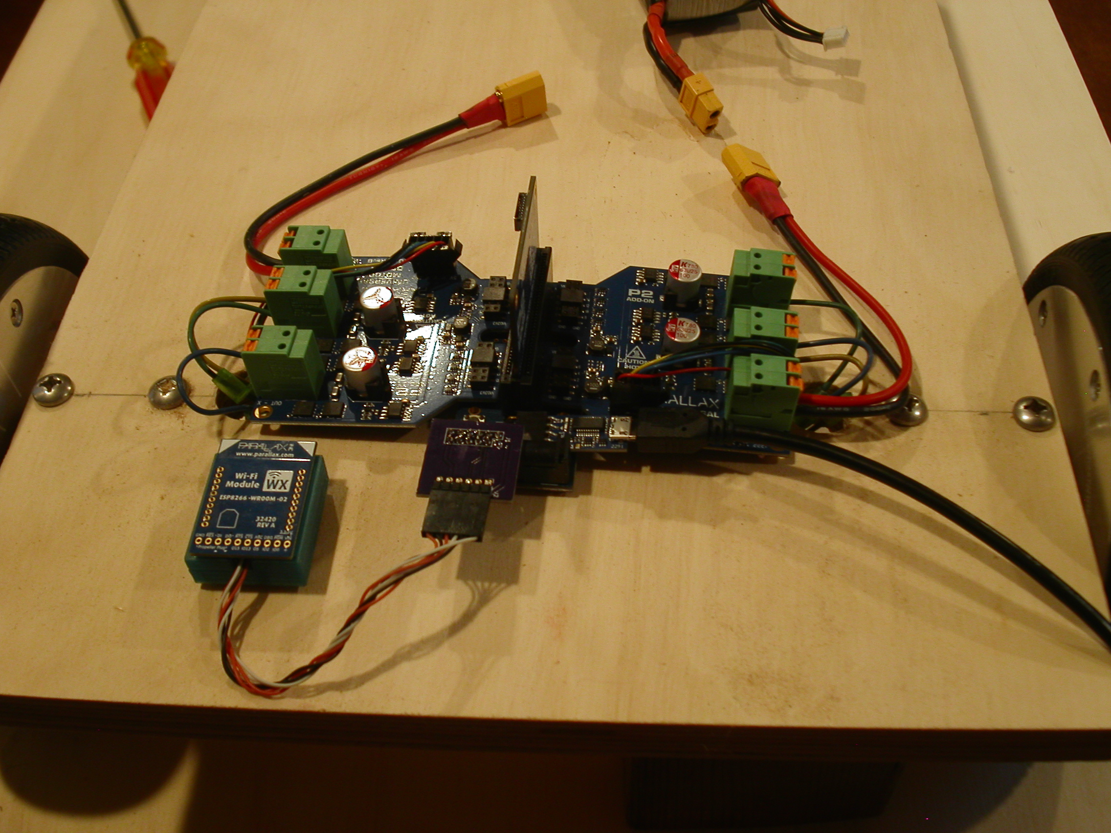
The new breakout board looks good. It has the 3 mm holes and has more room for the Wi-Fi adapter. With the Wi-Fi adapter I can program without the unit sitting on my lap.
Now to make a test area to put this together so I can build some code with the actual hardware in place. The 3/4 plywood turned out to be a tuff fit. The wires coming from the motors were very short and to plug them in to the BLDC board just made it as you can see from the picture the feedback cable was tight. Good thing I only made the board 12 inches wide.
Also trying to drill holes in a 3/4 plywood with a hand drill, not good. The measurements for the caster wheel were 1.375 inches apart. Don't have that on my ruler. I would suggest using a 1/4 piece of plywood as this would be easier to drill and give more length for the wires to fit through the holes in the board. Face it unless you're going to stand on this thing 3/4 inch is over kill.
Here is the setup with the new Edge breakout board installed.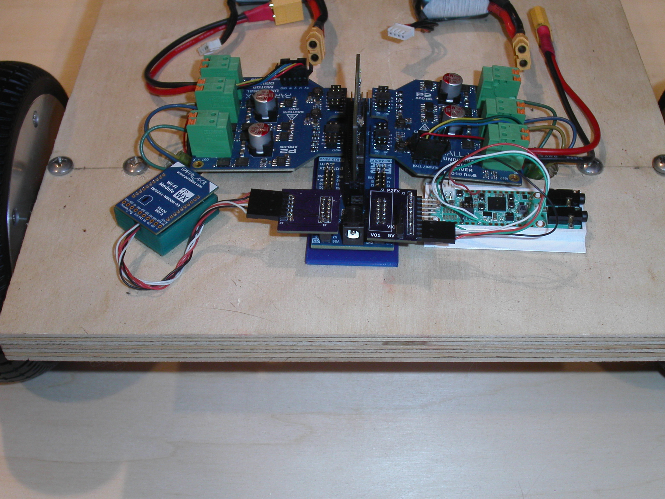
Now for the code. The internet suggests that a PWM frequency around 50Khz is a good choice to use to power the windings. The code is going to pulse the windings every 50 microseconds with the on state being only 30 microseconds. This would be about a 20Khz frequency.
I constructed an array of values to use for the commutation of the motor. Each phase must be in this order for the motor to move through each of the 6 steps.
char High[] = {0, 'W', 'W', 'V', 'V', 'U', 'U'};
char Low[] = {0, 'V', 'U', 'U', 'W', 'W', 'V'};
One of my problems was figuring out which socket was socket 00 and the other socket 02. The BLDC boards show the pin numbers but not which set of pins is J00 and J02. This led to a little trial and error and later programming issues using the wrong pin numbers.
I guess I should have looked closer at the second pdf drawing that showed the offset starting at 0 and going to 15. For the numbers to work out the sockets have to be in this order to work. Apparently I’m also not good at counting up to 16.
To drive this board bot I was going to use the MAX78000 and talk to my board. This turned out to be a problem with the motors making too much noise for it to understand what I was saying. The other thing is once it starts how do I stop it if it can’t hear me.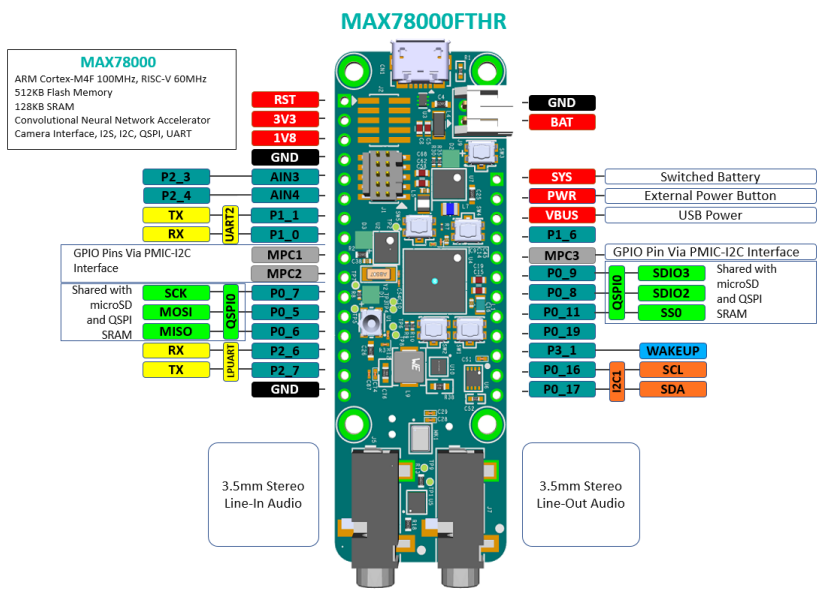
I picked up an ESP32 box that had a screen and Wifi built into it. It was about half the price of a P2 and was AI ready. To program it you need to use IDF from Espressif and that was not an issue for me. The screen was easy to setup since it used LVGL, a lightweight and open-source graphical library.
Now by putting the WX module in Station Access Point mode I could connect to the unit both through my network and the ESP32 unit could also connect to the Access Point.
With the ESP32 Dev kit connected to the WX module it was simply a matter of open a socket on port 23, which is the telnet port and send serial commands to the P2. The commands would be Forward, Left, Right, Backwards and Stop.
/**
 * @brief Drive Board Bot with remote controls
 * @author Michael Burmeister
 * @date April 16, 2025
 * @version 1.0
 *
*/

#include <stdio.h>
#include <stdlib.h>
#include <propeller.h>
#include "bldc.h"
#include "serial.h"
#include "fullduplex.h"

void DoFunction(void);


#define MAXRX 0
#define MAXTX 1
#define LEFT 32
#define RIGHT 16
#define SPEED 30


FILE *max;
char Buffer[256];
char Temp[256];
char ch;
int t;


int main(int argc, char** argv)
{
    int i;
    int x, y;
    int ld, rd;

    BLDC_Init(LEFT, RIGHT);

    BLDC_Enable();

    BLDC_Ticks(5000, 5000);

    FD_Init(230400);

    max = serial_open(MAXRX, MAXTX, 115200);

    serial_startFullDuplex(max);

    t=0;
    while (1)
    {
        i = FD_Check();
        if (i != 0)
        {
            ch = FD_Getch();
            if (ch == 0x0d)
            {
                DoFunction();
                t = 0;
            }
            else
            {
                Temp[t++] = ch;
                Temp[t] = 0;
            }

        }

        i = serial_count();
        if (i != 0)
        {
            _waitms(50);
            i = serial_readFullLine(Buffer);
            if (Buffer[0] != 'N')
                continue;

            printf("%s\n", Buffer);
            switch (Buffer[2])
            {
                case 'S':
                    Temp[0] = 'S';
                    break;
                case 'G':
                    Temp[0] = 'F';
                    break;
                case 'L':
                    Temp[0] = 'L';
                    break;
                case 'R':
                    Temp[0] = 'R';
                    break;
                case 'D':
                    Temp[0] = 'B';
                    break;

                default:
                    Temp[0] = 'S';
                    break;
            }
            Temp[1] = 0;
            DoFunction();
        }
    }
}

void DoFunction()
{
    int dl, dr;
    int s;

    dl = 0;
    dr = 0;
    s = 0;
    switch (Temp[0])
    {
        case 'S':
            s = 0;
            break;
        case 'F':
            dl = 0;
            dr = 0;
            s = SPEED;
            break;
        case 'L':
            dl = 1;
            dr = 0;
            s = SPEED;
            break;
        case 'B':
            dl = 1;
            dr = 1;
            s = SPEED;
            break;
        case 'R':
            dl = 0;
            dr = 1;
            s = SPEED;
            break;
        default:
            s = 0;
            break;

    }

//    printf("Cmd: %c\n", Temp[0]);

    BLDC_SetDirection(dl, dr);

    BLDC_SetSpeed(s, s);
}
Here is a short video of the board in action.
I tried talking to the unit but that didn't quite work but the ESP32 Dev kit did work.
Comments
Indeed, not the best behaved new baby")
Looks like a really solid start though - bet you'll have that thing tuned up in no time!
Good to see. Thanks.