

CasCade a cascaded motion controller
 ErNa
Posts: 1,862
ErNa
Posts: 1,862
This thread will document ideas and progress in the development of a simple motion controller. Chip in one of the last sessions presented the "jerk-based" generation of trajectories. This approach is very powerful and I finally have to bring forward a project, waiting for to long on my desktop.
To run my motor control experiments I have to set certain operating conditions quickly, and as using the proposed method trajectories can be define just by a list of jerks, this will be very handy.
Comments
intentionally left blank
intentionally left blank
intentionally left blank
A common positioning problem is to move from a starting point to a target point, acceleration, running at a certain speed and decelerate to finally stop at the target.
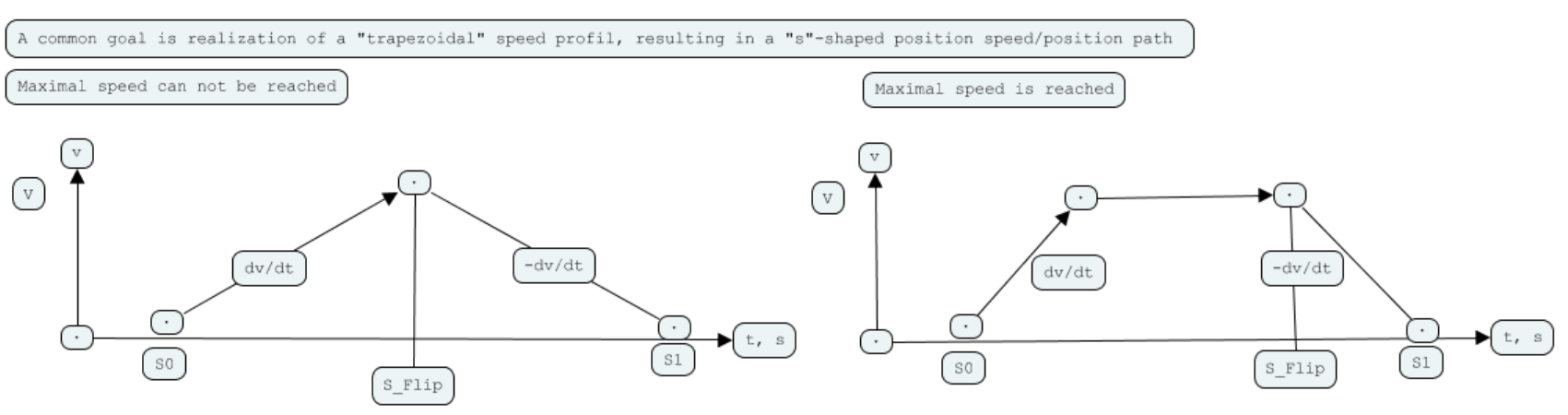
There is a given, limited acceleration and so it may happen, that you will not reach the top speed if the distance to travel is to short.
We will handle the task assuming ideal conditions, like there is no friction, torque is given, no lost steps when using stepper motors, no relevant inertia of the motor, no slip,.. etc. Also no tariffs.
Some minimal data should be available. Like time (a counter is running anyway in the propeller) and some measure for distance like steps of a stepper motor, sextant counter (Hall sensor for BLDC commutation), a incremental coder on a servo or even a linear scale.
How to control this path?
We start from position S0 with velocity zero and an acceleration of dv/dt, a constant value. In the first case we reach the middle of the path still accelerating, so we have to decelerate to reach the target S1with velocity zero.
The second case we reach the top speed and continue with constant speed till we reach the flipping point to decelerate.
Controlling this path need no more means, we have check for reaching top speed, sampling the distance SA, or reaching half the distance to travel. In the first case we set the flip-point to S1 - SA to determine the flip point and trigger deceleration as we reach it.
As Chip mentioned: jerk is the change in acceleration, so we only have to introduce a jerk, whenever acceleration has to change: 1, -2, 1 in the first case, 1, -1, -1, 1 in the second.
Two problems:
1) Assumption is accel and decel are the same rate
2) This won't work for s-curve profiles
Edit: A better method is to precalculate the maximum achievable velocity for the profile.
This is a work in progress and we have to identify the weak points one by one and find a work around. Acceleration is a consequence of force and inertia. , a law of nature. The jerk sets a value for the acceleration. And different values of jerk create different accel decel slopes. But why there is a difference? Just because bringing speed up is more difficult than bringing it down due to friction acting against or conform with the action intended. Also, any real profile is s-shaped, because not even jerk is a subject of sudden change. So if jerk itself is a triangle, the acceleration will start softly and this will influence the whole profile.
Everything we want to do in the real world is underlying certain limitations. You can not run around an edge with constant speed. But with a milling machine you may be able to do a loop, so the cutting speed stays constant. As all those complications exist, this project starts in an "ideal" world with inertia and instant jerk ;-)
But in an ideal world, averaging reduces noise. Averaging integrates a signal, consequently differentiation increases noise. And as the jerk is the third derivative of position ( speed, acceleration, jerk, ..) every tiny difference in jerk adds up to a large error. That means: the profile generated from a set of jerks will not be precise enough. You have to find a way to correct the path on certain occasions.
For this reason we break down the profile in single, elementary steps.
The "atom" of motor control is to reach a position at a given speed. This includes reaching a position at speed zero: remaining in this position. Reaching the position at speed zero means: there has to be a nonzero speed just before stopping. And in the simplest case this is done with constant acceleration, a linear decrease of speed and the zero crossing just at the target position.
An interesting comparison
The propeller allows us to easily run processes in parallel. Motion control may have different focus: constant feed rate when moving a laser, constant force on a mill, lowest deviation from a path, fastest sprint from point to point, etc. One way to flexibly handle those problems is, to have a general solution, that then is varied on request. So one process generates an optimal path, while another process actually drives the load, measuring the true path, while a third process evaluates a strategy to optimally reach the goal. The different processes can be developed independently, the path generator generated a certain contour. The driver drives the load and measures deviation, taking care not exceed performance limits like speed or torque. And only if this works perfectly, the "glue" process should be implemented. PMD shows, there is good reason to search for a more sophisticated solution, s-curve is not the end, rather the beginning.
The only time I designed my own profile I used sine/cosine maths. But, since it was a cam'd gear follower, it didn't have any start-stop ramping. Ramping was done by the master conveyor instead.
The cam'd acceleration was sine-like, disjointed at zero velocity, and combined with a flat gear ratio. It mimicked the adjustable pack length of older mechanical packaging machines from 50+ years ago. I never actually saw a mechanical working but they were pretty complicated and I was impressed they existed at all. The guy I contracted to repaired them for a living.
Annoyingly, I never kept any of my notes. And reading the comments now, the code says very little about the workings. It was almost 30 years ago!
Well I hope we can keep this thread going. The PMD devices are state-of-the-art but as I have been harping-on for years, the P2 can give them a run for their money. The PMD works-out @ ~US$32/axis.
They seem to be proud of their 10KHz loop-rate capability but I have had the P2 doing 100KHz, no sweat. Not something that is required much for me but I remember @ErNa being involved with nanometer resolutions.
However, I also have an app-note by Galil Motion Control somewhere, regarding nanometer-resolution positioning and they found no benefit beyond 4KHz.
Profiling:
-Trapezoidal
-S-Curve
-Parabolic
The most common but to be complete, we need to cater to on-the-fly changes to accel, slew, decel, target position.
And then there are virtual axes (without feedback and motor command) and electronic-gearing to consider.
Lots to do
")
While for physics "velocity" and "acceleration" are the right models, I have learned, that early thinking in "clock cycles per step of resolution" is helpful, if you have to write fast code. Sooner or later you have to convert to this scale anyways. Also it is helpful, to start ramps at a minimum speed instead of zero. Same for stop of course.
I am looking forward to see the cascaded driver. I often find it more easy to keep things more closely together, use only one Cog with common variables instead of more than one, which you have to keep synchronized.
@ErNa, is this about one axis or will it do interpolation with multiple axis?
Aka: Discretized. This is the standard method
When it comes to control loops, this is how I see it: If you have an acceleration of 1 G, that is 10 m/s², after one second you reach 10m/s, what gives an average speed of 5m/s and a distance of 5 m. 100 µs will result in a deviation of .5 mm. A control loop of 100 kHz will see a deviation of 50µm. But to react you have to have at least one PWM Cycle. And: the current ripple of the motor should not be more than 10%, so to reach full torque it will take about 10 PWM cycles. An external event creating 1G can not be controlled in short time. This shows the limits of a control structure. A disturbance creating 0.1 G could be handled in the "normal" error band. There is just one hope: as disturbances often come from resonances, they develop not in a moment and can be detected and predicted. What allows predictive control loops. We will see, how far we can go.
What is discussed here is independent of time scale. It can be applied to a self driving robot and the requirements are much lower, it's about the principles of control and gaining understanding. Hopefully it will work for trade rules too.
When it comes to multiple axes: if you follow a path you can see speed as a vector, located at a position. To follow a contour you have to change speed in direction of the vector and perpendicular. Knowing inertia and acceleration needed you can calculate and control the force for every axis separately, so multiple axes will not be the challenge. That's my hope...
The main idea for this cascade is: If you are moving fast, the system doesn't see rapid changes so you can determine your target and shoot into this direction. Whenever your control loop is entered, it will know the current state and so the deviation and can calculate the next action to reach the target. If you are decelerating, the time needed to reach the target is shrinking slower what will give you the chance to correct your path.
Anyway: a control system should only see a task, it can handle. It never has to be overloaded. Every exception has to be handled outside the control loop.
Problem being is that no mechanical elements that I'm aware of have such bandwidth.
Minimizing error during motion is typically handled by feedforwards. It's a no-brainer to achieve zero following error this way.