

OpenPNP and PandaPlacer
 Rayman
Posts: 16,461
Rayman
Posts: 16,461
Bought a PandaPlacer and just got it working.
It is all pretty awesome. Excellent use of OpenCV with the two cameras.
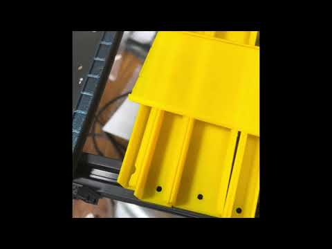
Made a video of the assembly:
Comments
Got some feedback from PandaPlacer and seems was missing a bearing and also there may be missed steps.
Didn't find missed steps, but did find that my son tripped over the USB cable and broke the connector.
All fixed now though:
I should mention the tariff...
UPS slapped me with a $450 tariff on the order because it was made in China and shipped from Canada.
So, if you want to order one, pay close attention to "de Minimus" and see if you can avoid that...
Just got 0402 part placement working! This is great:
It took me a while to figure out that there is a set screw on the feeder that has to be just right. Too tight and the tape doesn't advance right. Too loose and the parts fly out like popcorn when the tape advances.
Made a big mistake though and left the allen wrench in the set screw while using the machine. That sent the allen wrench flying across the room and bent something...
Had to realign the nozzle using a marker and a white sticker, as did during assembly. After that it works perfectly. Was pulling hair out for a while though until figured out that needed realignment...
Almost got it placing P2 correctly. One edge is off by one pin. Asked Pandaplacer for help, because no idea how to fix it...
Is the part center point part of your placement co-ordinate calculation? Sometimes if the symbol was not center aligned in whatever PCB software you exported the pick'n'place file from, then the ultimate place position would be off; at least until you apply a manual offset to the place co-ordinates. That one can be a real critter to catch.
I guess the outside dims might be another param to cause an offset?... I wonder how that camera works, and if it includes the legs when measuring. I suppose it shouldn't matter for a square part, but might be a factor with rectangular bodies. I've never tried a camera alignment system, so I might be thinking old school here; where entering the part dims is important for the part auto-centering function.
Think finally have it! Key was to enable "visual compositing". Had to actually read the manual to figure that one out
https://www.youtube.com/shorts/tlVqlXnv63s
Spot on! Doesn't get much closer than that !!
Am facing dilemma of switching to all 0603 or 0402, or sticking with 0805…
Think can place 0603 on 0805 pads so might do that as interim solution. Not sure though. Personally like the big 0805…
At same time 0402 is what I see on adafruit and sparkfun boards. So, maybe that is what should switch to…
If I have a lot of SMDs on a board I will start with 0805, then change to 0603 to do a final test before sending a PCB to a CM. I would dare try to hand-place 0402 devices.
So how much was this that it had a $450 tariff?
Might have been OK if had just ordered the machine for $790, just under de Minimus (at the time).
But, ordered it with two sets of the hardware for feeders at $30 each...
Imagine the situation is even worse now...
Now understand why one should put fiducials on PCBs... Seems the PNP is happiest when there are 3 on three corners of the board.
The "Platform Rev.A" board has no fiducials. But, does have some 0.6 mm vias with 0.9 mm OD. The PNP seems fine recognizing these as 1.0 mm fiducials. Got lucky here!
My advice: don't do it. I have a professional P&P machine that is capable of placing 0603 and 0402 reliably. But I still stick to 0805 for almost all of my components. They are much easier to handle and have much less tendency for tombstoning. The only case I could think of where you really want 0402 parts is between the vias on the bottom side of a large BGA IC. So you can place the bulk caps closer to the pins than you could with 0805 parts.
@ManAtWork That sounds like good advise. I also like being able to read resistance values...
Lost about 100 or so 0805 blue LEDs trying to get Bamboo Feeder to work with them in the black plastic tape. It just doesn't work reliably.
Thinking that these feeders only work with the white paper tape. Live and learn.
There is a "Strip Feeder" that is specifically meant for black plastic tape.
Printing some more of these out now...
Gearing up for p2 platform assembly tomorrow. Will be 100% awesome or complete disaster. Or maybe somewhere in between…
Fun in any event.